
Cutter surface plasma vacuum coating pretreatment process

A surface plasma and vacuum coating technology, used in ion implantation coating, vacuum evaporation coating, metal material coating process, etc., can solve the problems of poor coating adhesion, incomplete cutting edge, failure, etc. strength, preventing film cracking, and improving service life

Active Publication Date: 2019-01-11
合肥永信信息产业股份有限公司
View PDF4 Cites 5 Cited by
  • Summary
  • Abstract
  • Description
  • Claims
  • Application Information

AI Technical Summary

Problems solved by technology

[0005] 1. Inadequate removal of burrs at the cutting edge of the tool causes premature failure during its service;
[0006] 2. Improper selection of sandblasting process results in incomplete cleaning or edge damage;
[0007] 3. The choice of unreasonable cleaning process results in incomplete removal of microscopic stains on the surface of the tool and poor adhesion of the coating

Method used


Image

  • Cutter surface plasma vacuum coating pretreatment process
  • Cutter surface plasma vacuum coating pretreatment process
  • Cutter surface plasma vacuum coating pretreatment process

Examples


Embodiment 1

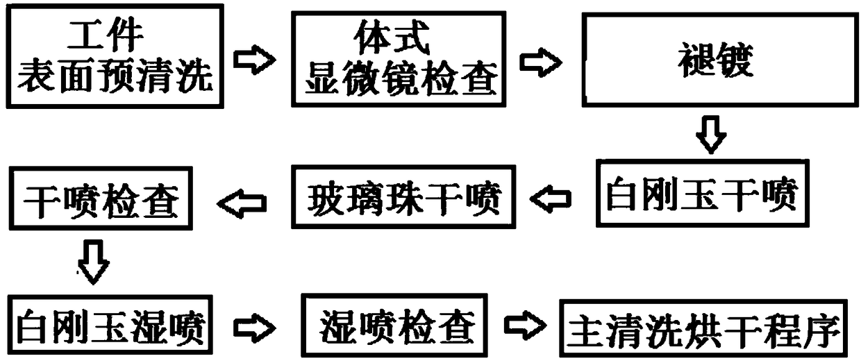
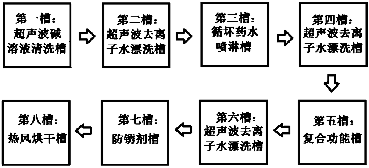
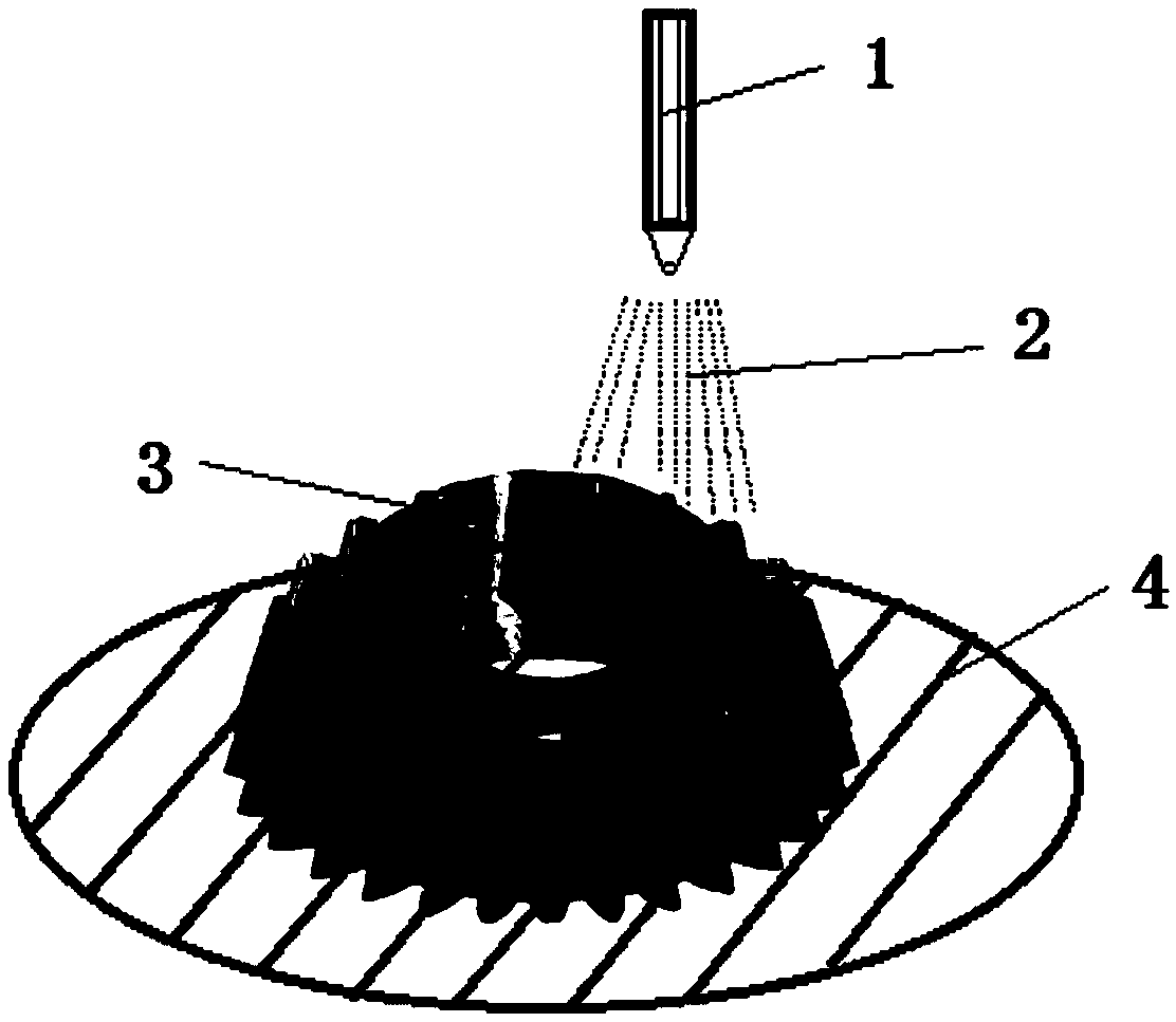
[0029] see figure 1 and figure 2 .

[0030] The pre-treatment process of plasma vacuum coating on the tool surface includes the following steps:

[0031] (1) Pre-cleaning of tool surface

[0032] There are usually a lot of oil stains, waxes and other pollutants on the surface of the cutting tool when the material comes in. Only after pre-cleaning to remove large macroscopic pollutants can it be convenient to observe the defects under the microscope. The surface pre-cleaning solution is the solution used in the first tank of the following main cleaning, so as to make full use of it, and the used surface pre-cleaning solution is used as hazardous waste for recycling.

[0033] (2) Stereo microscope inspection

[0034] After pre-cleaning, the tool is rinsed with clear water, dried with a high-pressure air gun, and then inspected under a stereo microscope. The inspection items include whether there are defects such as chipping, cracks, burrs, and blunt cutting edges on the sur...

Embodiment 2

[0063] Comparative experiment of different pretreatment processes

[0064] Table 2 is a comparison of different pretreatment processes, where the four processes A, B, C, and D correspond as follows:

[0065] A: Step (1)+(2)+(3)+(4)+(5)+(6)+(7)+(8)+(9);

[0066] B: Step (1)+(2)+(4)+(5)+(6)+(7)+(8)+(9);

[0067] C: step (1)+(2)+(3)+(4)+(7)+(8)+(9);

[0068] D: Step (1)+(2)+(3)+(4)+(5)+(6)+(9).

[0069] Table 2 Comparison of different pretreatment processes

[0070]

[0071] The surface cleanliness is based on the American ASTM D 2200 standard, in which SSPC SP1~10, the larger the number, the worse the surface cleanliness. It can be seen from Table 1 that B, C, and D in the four pretreatment processes will all cause the decline of the tool surface cleanliness , which has a greater impact on the bonding force between the coating and the substrate and the service life of the tool. The bonding force test adopts the German VDI3198 standard (HF1~HF6), HF1 represents the best bo...


PUM


Abstract

The invention discloses a cutter surface plasma vacuum coating pretreatment process which comprises the following steps: white corundum dry spraying; glass bead dry spraying; white corundum wet spraying; main cleaning; and drying. According to the cutter surface plasma vacuum coating pretreatment process disclosed by the invention, a sand blasting method which integrates the white corundum dry spraying operation, the glass bead dry spraying operation and the white corundum wet spraying operation is selected, so that residues on the surface of a cutter can be thoroughly removed; after the removal of burrs, the cutting edge of the cutter is rounded to a certain extent, so that the service life of the cutter can be effectively prolonged under the premise that the binding force is guaranteed;and for slotting cutters, the cutter surfaces can be effectively treated under the circumstance that cutting edges are protected, and the film layer and matrix binding force can be improved.

Description

technical field [0001] The invention relates to the field of vacuum coating, in particular to a pretreatment process of plasma vacuum coating on the surface of a tool. Background technique [0002] After the tool is treated with plasma vacuum coating, the surface hardness can be greatly improved. Compared with the uncoated tool, the tool life can usually be increased by several times or even ten times. Among the various links of vacuum coating, the most critical are the two links of pre-treatment and furnace coating. Improper pre-treatment, macroscopic stains remain on the surface of the tool, and ion cleaning is unable to remove them after entering the furnace, which will cause poor bonding or different degrees of film peeling off; On the surface, during the working process, the burrs fall off and cause the film layer to fall off, and the defects at the peeling place will gradually expand, eventually causing the entire film layer in the working area to fall off, and the to...

Claims


Application Information

Patent Timeline
Patent Type & Authority Applications(China)
IPC IPC(8): C23C14/02
CPCC23C14/021C23C14/028
Inventor 李灿民陶满李亚军
Owner 合肥永信信息产业股份有限公司
Learn More