
Industrial firing rotary kiln with kiln-in-kiln structure

A rotary kiln and industrial technology, applied in the field of industrial firing rotary kiln, can solve the problems of garbage size, hardness, properties, dry and humidity uncontrollable, unbalanced heat dissipation in the cooling zone, increased difficulty in processing, etc., to avoid problems such as The effect of the material being hung on the wall, shortening the firing time and shortening the drying time

Pending Publication Date: 2019-01-11
杨锡娟
View PDF0 Cites 1 Cited by
  • Summary
  • Abstract
  • Description
  • Claims
  • Application Information

AI Technical Summary

Problems solved by technology

[0003] Although the rotary kiln has been in operation in our country for quite a long time, some technical bottlenecks have not changed. Now the rotary kiln used in our country mainly has the following problems: First, in the continuous and uninterrupted production process of the rotary kiln, there will often be The second is that in the rotary kiln waste incineration, due to the uncontrollable size, softness, shape, and dry humidity of the waste, even after drying and crushing, some materials still cannot be broken, and even often entangled. In the crusher, the accumulation, extrusion, and adhesion into agglomerates cause rings to hang on the wall and insufficient combustion; the third is restricted by the inclination of the kiln body and the rotation speed of the cylinder body, the material forms a cross-sectional arc at the bottom of the kiln The rotation of the cylinder is only a slow displacement of the accumulation; the fourth is that the heating of the material in the kiln is unbalanced, and the cooling zone cannot dissipate heat evenly, resulting in that the material out of the kiln is not only high in temperature and The temperature of the discharged smoke and dust is also high, which increases the difficulty of subsequent treatment.

Method used


Image

  • Industrial firing rotary kiln with kiln-in-kiln structure
  • Industrial firing rotary kiln with kiln-in-kiln structure

Examples


Embodiment Construction

[0028] The following will clearly and completely describe the technical solutions in the embodiments of the present invention with reference to the accompanying drawings in the embodiments of the present invention. Obviously, the described embodiments are only some of the embodiments of the present invention, not all of them. Based on the embodiments of the present invention, all other embodiments obtained by persons of ordinary skill in the art without creative efforts fall within the protection scope of the present invention.

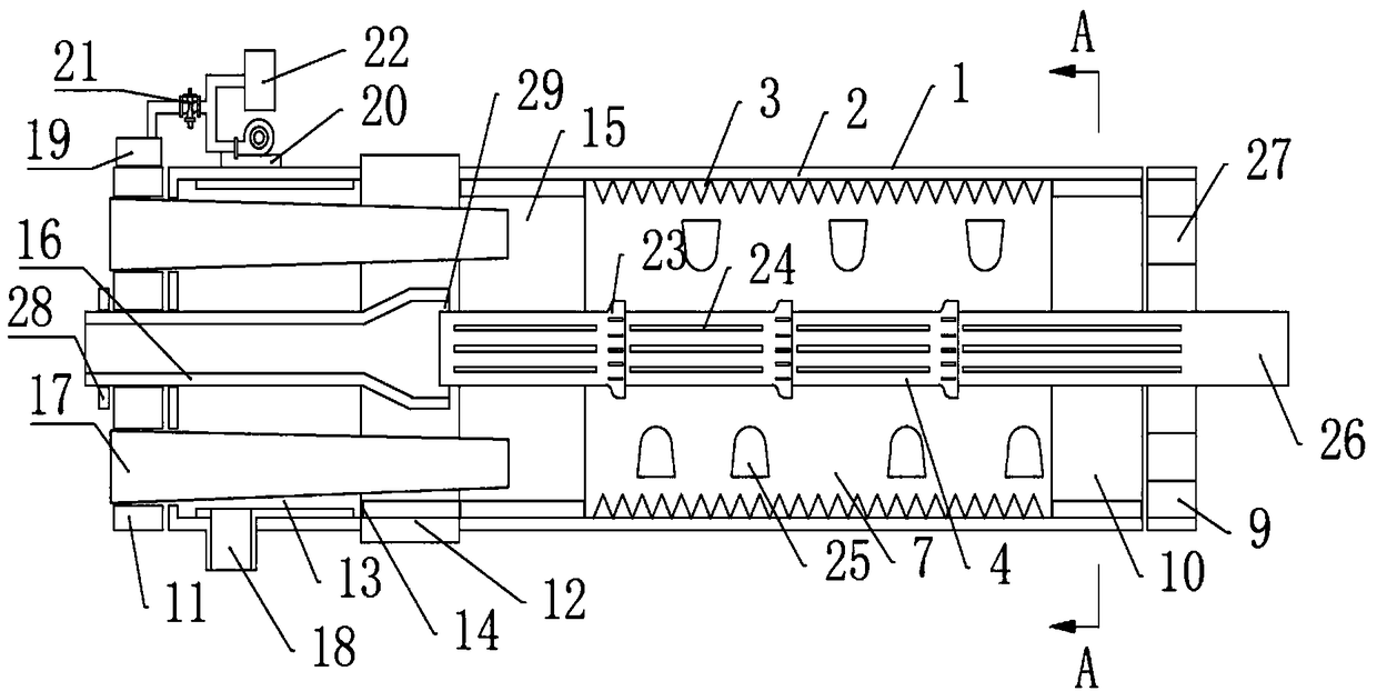
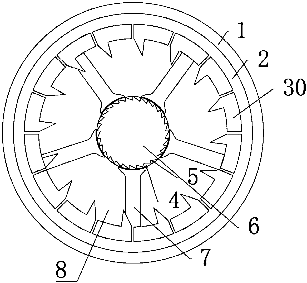
[0029] Such as figure 1 and figure 2 Commonly shown, the industrial firing rotary kiln with a kiln-in-kiln structure includes a rotary kiln shell 1, and the rotary kiln shell 1 includes an insulation layer 2. The inner side of the insulation layer 2 is provided with a toothed hook special-shaped refractory layer 3, and the rotary kiln barrel The inner center of the body 1 is provided with an inner kiln round pipe 4, and the inner wall of the inner k...


PUM


Abstract

The invention provides an industrial firing rotary kiln with a kiln-in-kiln structure. The industrial firing rotary kiln comprises a rotary kiln barrel body, the rotary kiln barrel body comprises a heat insulation layer and a toothed hook special-shaped flame retardant layer, an inner kiln circular pipe with the inner wall provided with inner kiln toothed hooks is arranged inside the rotary kiln barrel body, a plurality of supporting column walls are arranged in an outer kiln in a balanced mode, a heating space is formed between every two adjacent supporting column walls, the two ends of the rotary kiln barrel body are provided with a kiln tail cover and a kiln head cover correspondingly, an outer kiln centralized stock bin is formed between the kiln tail cover and the supporting column walls, the rotary kiln barrel body is provided with a transition cover, a cooling zone is formed between the transition cover and the kiln head cover, the bottom of the cooling zone is provided with a material feeding cooling zone channel port, a combustor placing chamber is formed between the transition cover and the supporting column walls, an inner kiln receiving pipe and a combustor are arrangedin the center inside the cooling zone, and the lower portion of the transition cover and the position leading to the cooling zone are each provided with a discharge outlet. The industrial firing rotary kiln has the advantages that the inner and outer filling rate is high, drying and combustion are sufficient, fuel energy consumption is low, combustion time is short, and energy conservation and emission reduction are achieved.

Description

technical field [0001] The invention relates to the technical field of environmental protection using building materials and equipment to co-process waste, in particular to an industrial firing rotary kiln with a kiln-in-kiln structure. Background technique [0002] "Green waters and lush mountains are golden mountains and silver mountains." Among them, resolutely winning the "Blue Sky Defense War" is the top priority of environmental governance. A large-scale investigation of pollution sources for energy conservation and emission reduction has been launched across the country. In addition to the excessive emission of motor vehicle exhaust that pollutes the environment, the emission of smoke and dust from industrial kilns is not up to standard, which is especially damaging to the atmospheric environment. Among them, the most harmful one is still the mixed dust mainly composed of dioxin, which poses a serious threat to air pollution. Secondly, all kinds of garbage, including...

Claims


Application Information

Patent Timeline
Patent Type & Authority Applications(China)
IPC IPC(8): F27B7/28F27B7/34
CPCF27B7/28F27B7/34
Inventor 杨全坤杨锡娟
Owner 杨锡娟
Learn More