A one-stage plasma catalysis in-situ diffuse reflectance infrared detection device
An infrared detection device and in-situ diffuse reflection technology, applied in the direction of measuring devices, separation methods, gas treatment, etc., can solve the problems of limiting the exploration of the synergistic mechanism of plasma catalysis and the inability to realize plasma discharge, etc., and achieve the effect of safe discharge process
- Summary
- Abstract
- Description
- Claims
- Application Information
AI Technical Summary
Problems solved by technology
Method used
Image
Examples
Embodiment 1
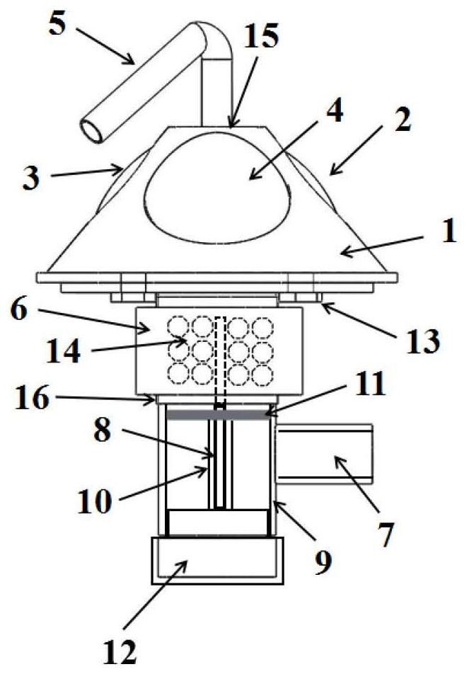
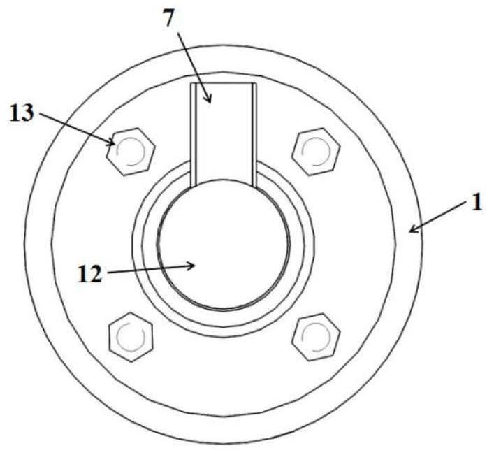
[0019] Example 1 A "one-stage" plasma-catalyzed in-situ diffuse reflectance infrared detection device, such as figure 1 The working gas shown in 2 and 2 enters the air chamber 14 from the intake pipe 5, the end of the intake pipe is connected with the top of the window support 1 by thread 15, 2 and 3 are zinc selenide windows and 4 is a quartz window, and the lower end of the observation window is connected with the discharge tube 9 And fixed by PTFE screw 13, the end of high-voltage electrode 8 is inserted into insulating pad 12, the top of high-voltage electrode 8 is inserted from bottom to top by the end of discharge tube 9, and the top of high-voltage electrode is fixed to be equal to the top of grounding electrode, and protective tube 10 is inserted into the bottom of high-voltage electrode 8 , the insulating ring 11 is inserted into the high-voltage electrode 8 and placed on the upper end of the protective tube 10, the right side of the discharge tube 9 is open and connec...
Embodiment 2
[0021] A "one-stage" plasma-catalyzed in-situ diffuse reflection infrared detection device, one end of the inlet pipe 5 is connected to the threaded port 15 at the center of the top of the conical shell 1, the three sides of the conical shell 1 are open, and the front is inlaid with a quartz window 4 for observation Window, the left and right sides have symmetrical openings and are inlaid with zinc selenide windows 2 and 3 as infrared windows. The bottom of the conical shell 1 is in contact with the flat part of the top of the discharge tube 9, and the contact surfaces of the two parts pass through four holes penetrating the two contact surfaces. The PTFE screw 13 is fixed so that the two parts are closely connected, and the ends of different PTFE screws 13 on the same plane are sequentially connected to form a square. One end of the discharge tube 9 is connected to the bottom end of the conical shell 1, and the other end is an insulating pad 12. A fixed ring 11 is arranged par...
PUM
 Abstract
Description
Claims
Application Information
 - R&D
- Intellectual Property
- Life Sciences
- Materials
- Tech Scout
- Unparalleled Data Quality
- Higher Quality Content
- 60% Fewer Hallucinations
Browse by: Latest US Patents, China's latest patents, Technical Efficacy Thesaurus, Application Domain, Technology Topic, Popular Technical Reports.
© 2025 PatSnap. All rights reserved.Legal|Privacy policy|Modern Slavery Act Transparency Statement|Sitemap|About US| Contact US: help@patsnap.com


