
Method for calculating chamfering of tooth tip of spiral bevel gear based on discretization of curved surface

A discretization technology for spiral bevel gears, which is applied in the field of calculation and processing of spiral bevel gear tooth top chamfering, which can solve the problems of low production efficiency and machining errors

Inactive Publication Date: 2019-01-11
YANGTZE UNIVERSITY
View PDF0 Cites 9 Cited by
  • Summary
  • Abstract
  • Description
  • Claims
  • Application Information

AI Technical Summary

Problems solved by technology

[0003] The object of the present invention is to provide a method for processing spiral bevel gear tooth tip chamfering with a four-axis CNC machine tool based on surface discretization to solve the problems of low production efficiency and large processing errors in manual chamfering

Method used


Image

  • Method for calculating chamfering of tooth tip of spiral bevel gear based on discretization of curved surface
  • Method for calculating chamfering of tooth tip of spiral bevel gear based on discretization of curved surface
  • Method for calculating chamfering of tooth tip of spiral bevel gear based on discretization of curved surface

Examples


Embodiment Construction

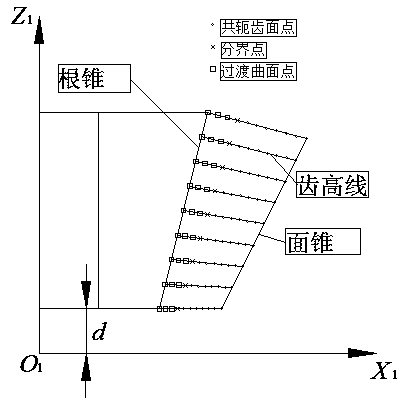
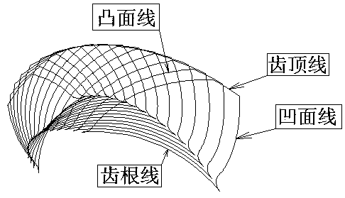
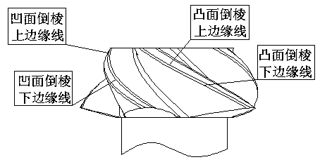
[0085] The chamfer calculation method first creates a gear solid model according to the tooth surface mathematical model, and then creates the tooth tip chamfer feature on the gear solid model. Extract the discrete point coordinates of the upper and lower edge lines of the tooth top chamfer, take the distance between the ball center of the ball end mill and the chamfer edge line as the constraint condition, and use the numerical algorithm to solve the chamfer ball end mill path . According to the relationship between the axis direction of the ball end mill and the contact position of the surface of the ball end mill, the direction angle of the cutter axis can be changed uniformly within the feasible range, so that the contact position between the ball end mill and the tooth top can be evenly distributed on the ball end end mill surface. Install the non-chamfered gear on the four-axis machine tool, complete the axial and circumferential tool setting of the gear through the edg...


PUM


Abstract

The invention relates to a method for calculating the chamfering of the tooth tip of a spiral bevel gear, in particular to a method for calculating the chamfering of the tooth tip of the spiral bevelgear based on the discretization of a curved surface. The chamfering calculation method comprises the steps of: firstly creating a gear solid model according to the mathematical model of the tooth surface, and then creating a chamfering feature expression on the gear solid model, extracting the coordinates of the discrete points of the upper and lower edge lines of the chamfering tooth top, and obtaining the chamfering ball-end milling cutter path by numerical algorithm; according to the relationship between the axial direction of the ball end milling cutter and the contact position of the surface of the ball end milling cutter, installing the unchamfered gear on the four-axis machine tool, and completing the axial and circumferential tool alignment of the gear through the edge finder, andcompleting the chamfering of the tooth tip according to the ball-end milling cutter path. The chamfering calculation method can make the chamfering of tooth tip be finished by a four-axis machine, and solve the problems of low production efficiency and big machining error in manual chamfering, and meet the needs of production and use of enterprises.

Description

technical field [0001] The invention relates to a calculation and processing method for the tooth top chamfer of a spiral bevel gear, in particular to a calculation method for the tooth top chamfer of a spiral bevel gear based on discretization of a curved surface. Background technique [0002] Spiral bevel gear is a transmission component used to transmit the motion between intersecting shafts or intersecting shafts. It has the advantages of large coincidence, stable transmission, and strong bearing capacity. After the tooth surface of the spiral bevel gear is processed, the tooth surface and the top of the tooth will form a sharp angle. Under the influence of gear manufacturing errors and installation errors, noise, impact, and rapid fatigue damage on the tooth surface will occur during gear meshing transmission. Therefore, it is necessary to The tooth top chamfering is performed to remove the tooth tip angle. At present, the chamfering of the tooth top of the spiral beve...

Claims


Application Information

Patent Timeline
IPC IPC(8): G06F17/50G06T17/20G06N3/00B23F19/10
CPCB23F19/102G06F30/23G06N3/006G06T17/20
Inventor 魏巍
Owner YANGTZE UNIVERSITY
Learn More