Polishing pad and method for manufacturing same, and method for manufacturing abrasive

A manufacturing method and a technology of grinding pads, which are applied in the direction of grinding machine tools, manufacturing tools, grinding tools, etc., can solve the problems of difficult operation of metal platforms, labor-intensive maintenance and management, etc., and achieve the effect of excellent surface quality and excellent grinding rate

Active Publication Date: 2019-01-11
FUJIBO HLDG
View PDF9 Cites 0 Cited by
  • Summary
  • Abstract
  • Description
  • Claims
  • Application Information

AI Technical Summary

Problems solved by technology

[0013] However, metal-based platforms are difficult to handle due to their weight, and maintenance and management after use, such as maintenance of the surface of the platform embedded with diamond abrasive grains, requires labor.

Method used


Image

  • Polishing pad and method for manufacturing same, and method for manufacturing abrasive
  • Polishing pad and method for manufacturing same, and method for manufacturing abrasive
  • Polishing pad and method for manufacturing same, and method for manufacturing abrasive

Examples


Embodiment 1

[0213] (one impregnation process)

[0214] 56.7 parts by mass of polycarbonate-based urethane resin (manufactured by DIC Corporation, trade name "CRISVON S705") and 43.3 parts by mass of N,N-dimethylformamide were mixed to prepare a resin solution. The knitted fabric A was dipped in the obtained resin solution, and the excess resin solution was squeezed off with a nip roll, thereby impregnating the knitted fabric A substantially uniformly with the resin solution. Next, the knitted fabric A was immersed in a coagulation solution containing water at 18° C., whereby the primary impregnated resin was coagulated and regenerated to obtain a resin-impregnated knitted fabric. Then, the resin-impregnated knitted fabric was taken out from the coagulation solution and dried to obtain a resin-impregnated knitted fabric from which the surface skin layer was removed by buffing.

[0215] (dipping process)

[0216] Next, the resin-impregnated knitted fabric obtained above was immersed in an...

Embodiment 2

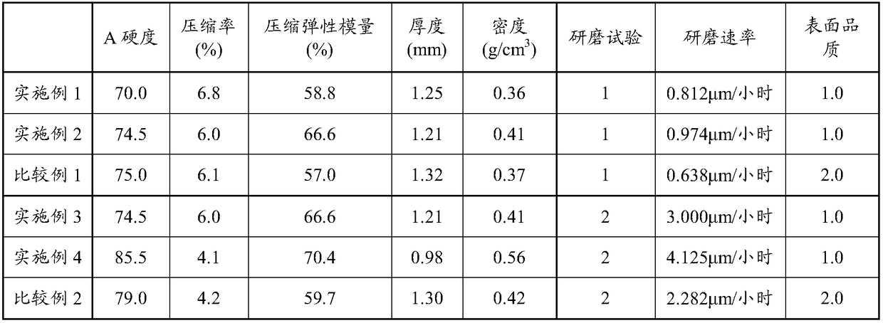
[0222] In addition to adjusting the nip condition of the nip roll so that the density of the polishing pad becomes 0.41 g / cm 3 Except that, the polishing pad of Example 2 was obtained by the method similar to Example 1. The knitted fabric content was 32 mass % with respect to the whole polishing pad.

Embodiment 3

[0226] The polishing pad of Example 3 was obtained in the same manner as in Example 2, except that grooves having a U-shaped cross section with a pitch of 30 mm, a width of 2 mm, and a depth of 0.5 mm were provided on the polishing surface. The knitted fabric content was 32 mass % with respect to the whole polishing pad.


PUM

PropertyMeasurementUnit
Number average diameteraaaaaaaaaa
Thicknessaaaaaaaaaa
Melting pointaaaaaaaaaa

Abstract

Provided is a polishing pad having a knit fabric configured from a warp and a weft, and a resin with which the knit fabric is impregnated, the polishing pad having a cross-section cut along the direction of the surface of the knit fabric as a polishing surface.

Description

technical field [0001] The present invention relates to a polishing pad, a method for manufacturing the same, and a method for manufacturing abrasives. Background technique [0002] In recent years, for next-generation power semiconductor element materials, silicon carbide (SiC), gallium nitride (GaN), diamond (C), sapphire (Al 2 o 3 ) and aluminum nitride (AlN) and other materials have attracted attention. For example, silicon carbide (SiC) has excellent physical properties such as three times the band gap and about seven times the dielectric breakdown electric field strength compared with silicon (Si) semiconductors. It is excellent in terms of excellent performance, small size, and high energy-saving effect. In addition, for sapphire wafers, due to its chemical stability, optical properties (transparency), mechanical strength, thermal properties (thermal conductivity), etc., it is used as a component for electronic equipment with optical elements, such as high-performa...

Claims


Application Information

Patent Timeline
IPC IPC(8): B24B37/24H01L21/304
CPCB24B37/24B24D3/28B24D11/003H01L21/304H01L21/02B24B37/044D06M2200/35D06M23/10D06M13/127D04B1/12D04B1/22D06M15/564
Inventor 德重伸中濑惠介柏田太志山田龙也楢田洋祐小池坚一
Owner FUJIBO HLDG
Why Eureka
Try Eureka