
A covered stent

A covered stent and film-covered technology, which is applied in the field of vascular stents, can solve problems such as complications, complicated operation, and increased incidence of covered stent shedding or migration, and achieve the effect of convenient implantation and ensuring stability

Active Publication Date: 2019-01-15
BEIHANG UNIV
View PDF4 Cites 1 Cited by
  • Summary
  • Abstract
  • Description
  • Claims
  • Application Information

AI Technical Summary

Problems solved by technology

However, a large number of case follow-up records found that there are still a certain proportion of patients with postoperative complications
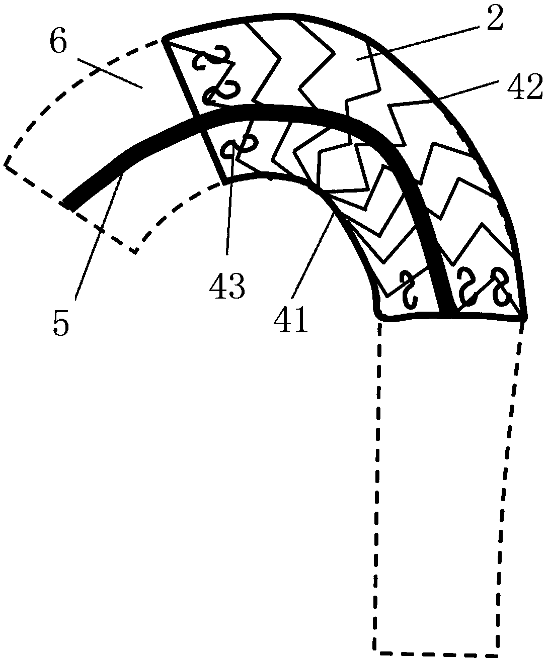
[0003] According to the detection of stent grafts in patients, the following problems will occur after implantation of stent grafts: Since the commonly used aortic stent grafts are straight before implantation, after implantation of the curved aortic arch, the rigidity of the material itself will cause problems. Causes the ends of the stent graft to "twist" to match the curved configuration of the aortic arch
On the one hand, both ends of the stent-graft compress or even damage the outer local vessel wall of the aortic arch, leading to complications; May increase the incidence of stent graft shedding or migration, and induce aortic wall damage
[0004] In response to the above-mentioned problems, some stent grafts in the prior art are shaped to match the curved aortic arch during production, which can reduce the rebound force generated by the existing stent graft after passive bending of the aortic arch. , but the stent-graft is shaped into a curved shape in vitro, and special equipment is needed to help implant the stent-graft into the aortic arch, which increases the cost of implantation and is more complicated to operate

Method used


Image

  • A covered stent
  • A covered stent
  • A covered stent

Examples


Embodiment 2

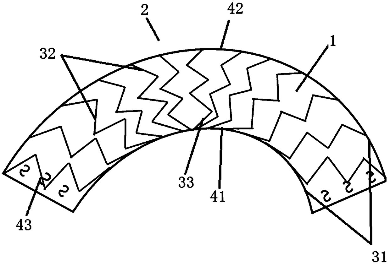
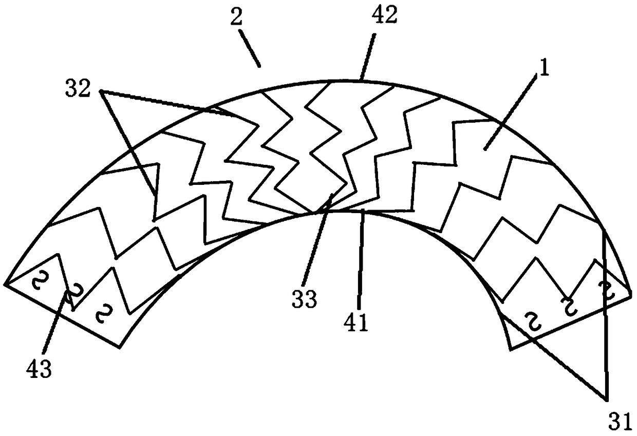
[0050] The difference between this embodiment and Embodiment 1 is that, if Figure 4 with Figure 5 As shown, the membrane 1 is in a curved state before implantation, and the frame body is in a straight state before implantation; and the length of the membrane 1 before implantation at the curved inner side 41 of the tubular structure 2 is, Less than the pre-implantation length at the curved outer side 42 of the tubular structure 2 . The membrane 1 before implantation is provided with wave-shaped folds 11 at the curved inner side 41 of the tubular structure 2 , and the frame body is sheathed on the outer side of the membrane 1 .

[0051] The wavy folds 11 allow the membrane to have a small space for adjusting the curvature of the membrane 1 to better match the aortic arch, and can effectively prevent the stent graft from falling off or the mobility of the stent graft under the impact of blood flow. Induces damage to the aortic wall.

[0052] The manufacturing method of the c...

Embodiment 3

[0056] The difference between this embodiment and Embodiment 2 is that, as Figure 4 As shown, in this embodiment, the membrane 1 is in a bent state before implantation, and the frame body is in a straight state before implantation. The frame body includes a keel 31 and a bracket 32 ​​. The keel 31 is long and has two pieces, which are respectively arranged on the inner side 41 and the outer side 42 of the tubular structure 2 when it is bent. There are multiple brackets 32, which are in a zigzag ring structure. The multiple brackets 32 are connected by the keel 31, and when the tubular structure 2 is in a straight state, the brackets 32 are evenly arranged on the keel 31 superior.


PUM


Abstract

The invention belongs to the field of vascular stents, in particular to a covered stent. The covered stent comprises a frame body; a membrane disposed on the frame body to form a tubular structure. The tubular structure is in a bent state before implantation. One of the membrane and the frame body is in a bent state before implantation, and the other is in a straight state before implantation. The covered stent of the invention is simple in implantation and can be matched with a curved aortic arch.

Description

technical field [0001] The invention belongs to the field of vascular stents, in particular to a covered stent. Background technique [0002] Aortic aneurysm and aortic dissection are frequent diseases in the cardiovascular system. Among them, aortic aneurysm is manifested by local expansion of the artery, and the mechanical properties of the vessel wall are reduced. After the condition worsens, it is easy to cause aneurysm rupture, and the mortality rate is extremely high. Media and adventitia, caused by the formation of false lumen, the most serious result is dissection rupture and bleeding, the rupture process is very painful and the mortality rate is also high. At present, both diseases can be treated by implanting a covered stent, which separates the blood from the vessel wall and prevents the blood flow from directly acting on the vessel wall. However, a large number of case follow-up records found that there are still a certain proportion of patients with postoperat...

Claims


Application Information

Patent Timeline
Patent Type & Authority Applications(China)
IPC IPC(8): A61F2/07
CPCA61F2/07A61F2002/075
Inventor 孙安强杨雅清樊瑜波邓小燕
Owner BEIHANG UNIV
Learn More