

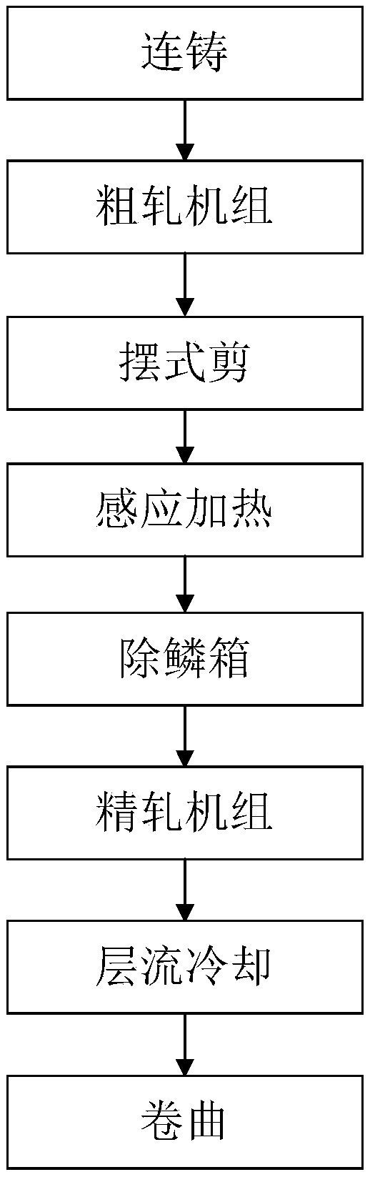
Finishing rolling unit in ESP endless rolling and rolling method
A finishing mill and endless rolling technology, applied in metal rolling, metal rolling, manufacturing tools, etc., can solve the problems of not being able to fully release production capacity, not having the function and strategy of online roll changing with dynamic rules, and achieving The comprehensive economic benefits of the enterprise are considerable, the production cycle is shortened, and the effect of reducing heating energy consumption
- Summary
- Abstract
- Description
- Claims
- Application Information
AI Technical Summary
Problems solved by technology
Method used
Image

Examples
Embodiment 1
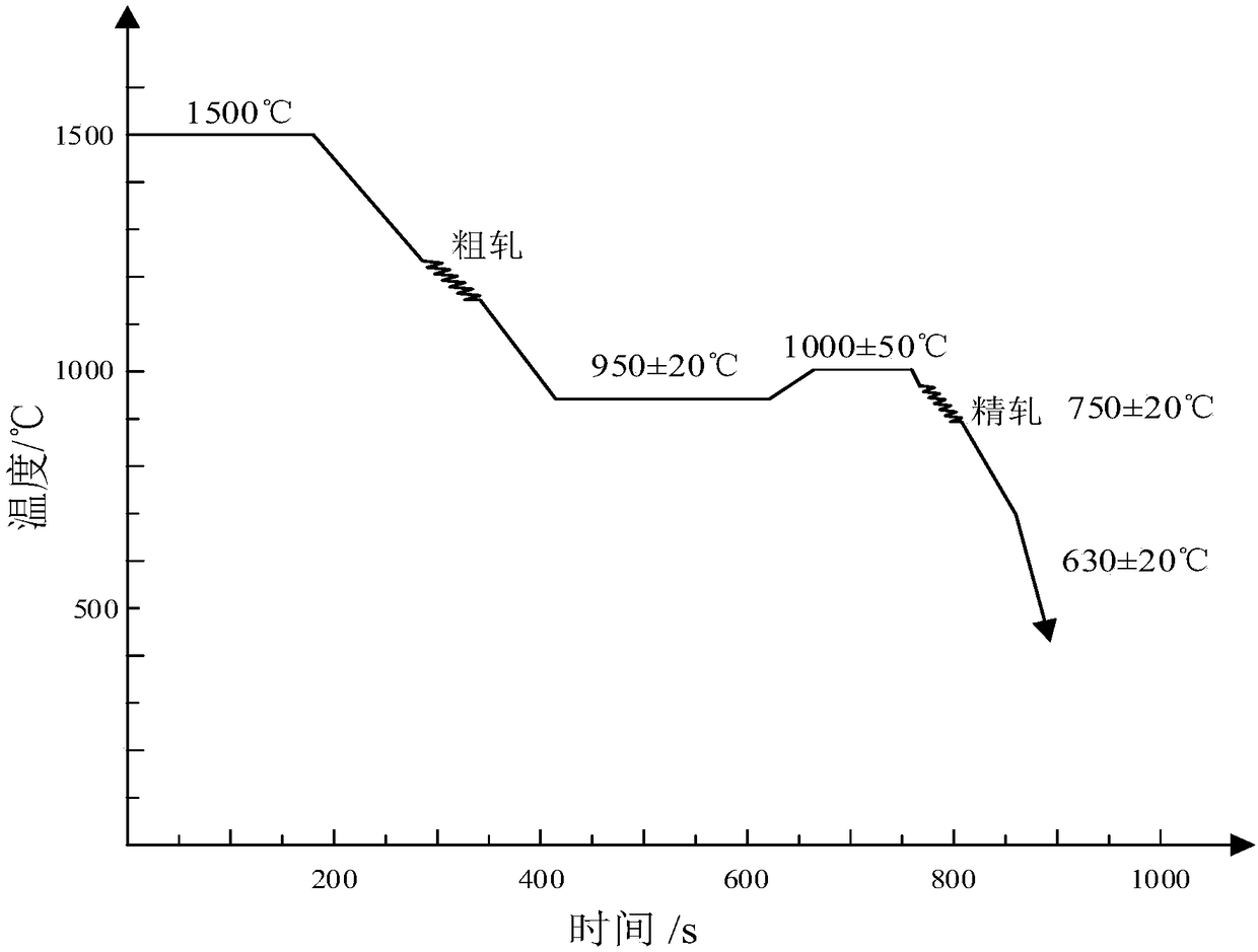
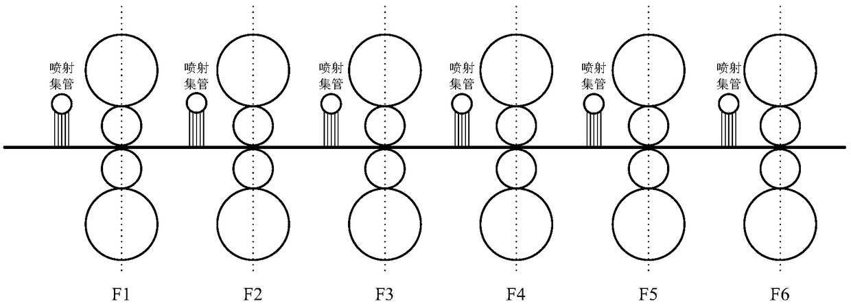
[0046] Such as image 3 As shown, in the present invention, when F1 is the standby finishing mill, and F3 is the worn finishing mill, the strip blank at 1500°C after continuous casting, the outlet temperature of the third stand of the rough rolling group is 930°C, and the temperature is 950°C after induction heating. ℃, the microstructure of the billet is austenite, and it is in the austenite zone before entering the finishing rolling unit. After being rolled by the finish rolling mill, the temperature of the last stand of the strip billet is 730°C after passing through the finish rolling mill, and the temperature drops to 610°C after laminar flow cooling.
[0047] When the rolls of the F3 frame need to be replaced, the dynamic variable regulation downstream adjustment strategy is adopted. At this time, the injection header in front of the F1 frame starts to spray cooling water to the strip, and the injection header in front of the F1 frame sprays the strip. After the cooling...
Embodiment 2
[0049] Such as image 3 As shown, in the present invention, when F1 is the standby finishing mill, and F3 is the worn finishing mill, the strip billet at 1500°C after continuous casting passes through the third stand of the rough rolling mill. ℃, the microstructure of the billet is austenite, and it is in the austenite zone before entering the finishing rolling unit. After being rolled by the finish rolling mill, the temperature of the last stand of the final strip is 750°C in the finish rolling mill, and the temperature drops to 630°C in laminar flow cooling.
[0050] When the rolls of the F3 frame need to be replaced, the dynamic variable regulation downstream adjustment strategy is adopted. At this time, the injection header in front of the F1 frame starts to spray cooling water to the strip, and the injection header in front of the F1 frame sprays the strip. After the cooling water, the finish rolling unit starts to change rolls online. At this time, F3 is raised and F1 i...
Embodiment 3
[0052] Such as image 3 As shown, in the present invention, when F1 is the standby finishing mill, and F3 is the worn finishing mill, the strip billet at 1500°C after continuous casting passes through the third stand of the rough rolling mill. ℃, the microstructure of the billet is austenite, and it is in the austenite zone before entering the finishing rolling unit. After being rolled by the finish rolling mill, the temperature of the last stand of the strip billet is 770°C after passing through the finish rolling mill, and the temperature drops to 650°C after laminar flow cooling.
[0053] When the rolls of the F3 frame need to be replaced, the dynamic variable regulation downstream adjustment strategy is adopted. At this time, the injection header in front of the F1 frame starts to spray cooling water to the strip, and the injection header in front of the F1 frame sprays the strip. After the cooling water, the finish rolling unit starts to change rolls online. At this time...
PUM
| Property | Measurement | Unit |
|---|---|---|
| thickness | aaaaa | aaaaa |
Abstract
Description
Claims
Application Information