Method for manufacturing covered edge of fan blade

A technology for fan blades and manufacturing methods, applied in the field of fan blade wrapping, can solve the problems of affecting the aerodynamic efficiency of the blades, large residual stress, and low processing efficiency, so as to meet the requirements of aerodynamic design, enhance fatigue resistance, and use materials rate-enhancing effect

Inactive Publication Date: 2019-01-15
AVIC BEIJING AERONAUTICAL MFG TECH RES INST
View PDF4 Cites 11 Cited by
  • Summary
  • Abstract
  • Description
  • Claims
  • Application Information

AI Technical Summary

Problems solved by technology

[0007] At present, titanium alloy edge wrapping at the leading edge of composite material blades is generally manufactured through forgings / thick plate CNC processing, and the material utilization rate is less than 10%; the requirements for forging, numerical control and other equipment and tooling molds are high, and the processing efficiency is low; and because the edge wrapping It is a thin-walled and complex curved surface structure with poor rigidity, large machining deformation, and low machining accuracy, which affects the aerodynamic efficiency of the blade; the residual stress generated by cutting is large, which affects the performance of the wrapping; the surface quality is not high, and usually requires subsequent polishing treatment

Method used


Image

  • Method for manufacturing covered edge of fan blade
  • Method for manufacturing covered edge of fan blade
  • Method for manufacturing covered edge of fan blade

Examples


Embodiment Construction

[0022] Embodiments of the present invention are described in detail below, examples of which are shown in the drawings, wherein the same or similar reference numerals designate the same or similar elements or elements having the same or similar functions throughout. The embodiments described below by referring to the figures are exemplary and are intended to explain the present invention and should not be construed as limiting the present invention.

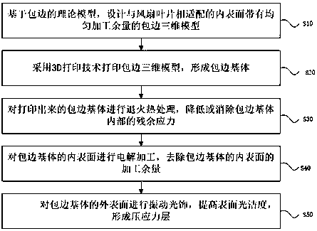
[0023] The invention provides a method for manufacturing fan blade wrapping, such as figure 1 shown, including:

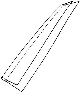
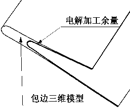
[0024] Step S10 , based on the theoretical model of wrapping, designing a three-dimensional wrapping model with a uniform machining allowance on the inner surface suitable for the fan blade.

[0025] Step S20, using 3D printing technology to print the 3D model of the hemming to form the hemming matrix. This step specifically includes: along the fan blade spanwise, discretize the 3D model with uniform machining allow...


PUM


Abstract

Aiming at a composite material fan blade, the invention provides a method for manufacturing the covered edge of the fan blade. The method comprises the following steps that for a theoretical model based on the covered edge, an edge covering three-dimensional model which is matched with the fan blade and is provided with a uniform machining allowance is designed; a 3D printing technology is adoptedto print the edge covering three-dimensional model to form an edge covering base body; annealing heat treatment is carried out on the printed edge covering base body, so that residual stress inside the edge covering base body is reduced or eliminated; electrolytic machining is conducted on the inner surface of the edge covering base body, so that the machining allowance of the inner surface of the edge covering base body is removed; and vibration finishing is carried out on the outer surface of the edge covering base body, so that the surface smoothness is improved, and a compressive stress layer is formed. The method aims to fully utilize the 3D printing technology to achieve the following advantages that the material utilization rate is high, the surface quality of an electrolytic machining part is good, the residual stress and deformation are small, the surface quality of a part machined through vibration finishing is good, and the anti-fatigue strength can be improved to a certaindegree; and near-no-allowance machining of edge covering is realized, the material utilization rate and the machining precision are improved, and the cost is saved.

Description

technical field [0001] The invention relates to the technical field of fan blade processing, in particular to a method for manufacturing fan blade wrapping. Background technique [0002] Compared with titanium alloy fan blades, composite material fan blades have the advantages of high weight reduction efficiency, low fuel consumption, and good vibration resistance, but they also have disadvantages such as poor bird strike resistance and easy delamination and cracking. In the civil high bypass ratio turbofan engines already in service, such as GE90 and GEnx, the method of bonding titanium alloy wrapping on the leading edge of the blade is mainly used to improve the anti-strike ability of the leading edge. [0003] Due to the requirements of aerodynamic design, fan blades generally have a sweeping structure with curved space, so the leading edge wrapping is usually a thin-walled complex three-dimensional curved surface structure with large size, poor rigidity, and high surface...

Claims


Application Information

Patent Timeline
Patent Type & Authority Applications(China)
IPC IPC(8): B23P15/00B22F3/105B22F3/24
CPCB22F3/24B23P15/00B22F10/00B22F10/62B22F10/66B22F10/64B22F10/25Y02P10/25
Inventor 韩晓宁张兴振李志强邵杰
Owner AVIC BEIJING AERONAUTICAL MFG TECH RES INST
Why Eureka
Try Eureka