
Anti-magnetic levitation wind power energy collector

An energy harvester and magnetic levitation technology, which is used in wind energy generation, wind turbines, wind turbine combinations, etc., can solve the problems of inability to generate electricity, wind direction requirements, and large friction of components, so as to improve the utilization rate of wind energy, increase the wind area, The effect of omitting the bearing structure

Inactive Publication Date: 2019-01-15
ZHENGZHOU UNIV
View PDF8 Cites 0 Cited by
  • Summary
  • Abstract
  • Description
  • Claims
  • Application Information

AI Technical Summary

Problems solved by technology

At present, the commonly used wind power generators usually fix the generator on the upper end of the pole or tower through the connecting flange, and directly fix the rotating shaft of the wind blade on the top of the generator. Or it cannot generate electricity when there is a slight wind, and most generators have requirements for the wind direction. During the power generation process, the wind direction needs to be adjusted continuously, which makes the operation troublesome. When the fan is running, the friction between the parts is large, the energy consumption is high, and the conversion rate is low.
Now people apply the magnetic levitation technology to the support of the wind turbine rotor, and replace the traditional mechanical bearing with the magnetic levitation bearing. Although the friction between the rotor and the bearing is greatly reduced and the power generation efficiency is improved, the rotating part and the non-rotating The mechanical friction between parts still exists, and a certain amount of cut-in wind is also required, which is not suitable for promotion and use in areas with low wind speed all year round

Method used


Image

  • Anti-magnetic levitation wind power energy collector
  • Anti-magnetic levitation wind power energy collector
  • Anti-magnetic levitation wind power energy collector

Examples


Embodiment Construction

[0023] The present invention will be further described below in conjunction with accompanying drawing.

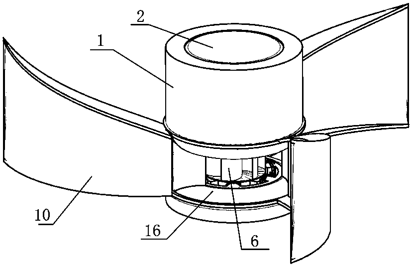
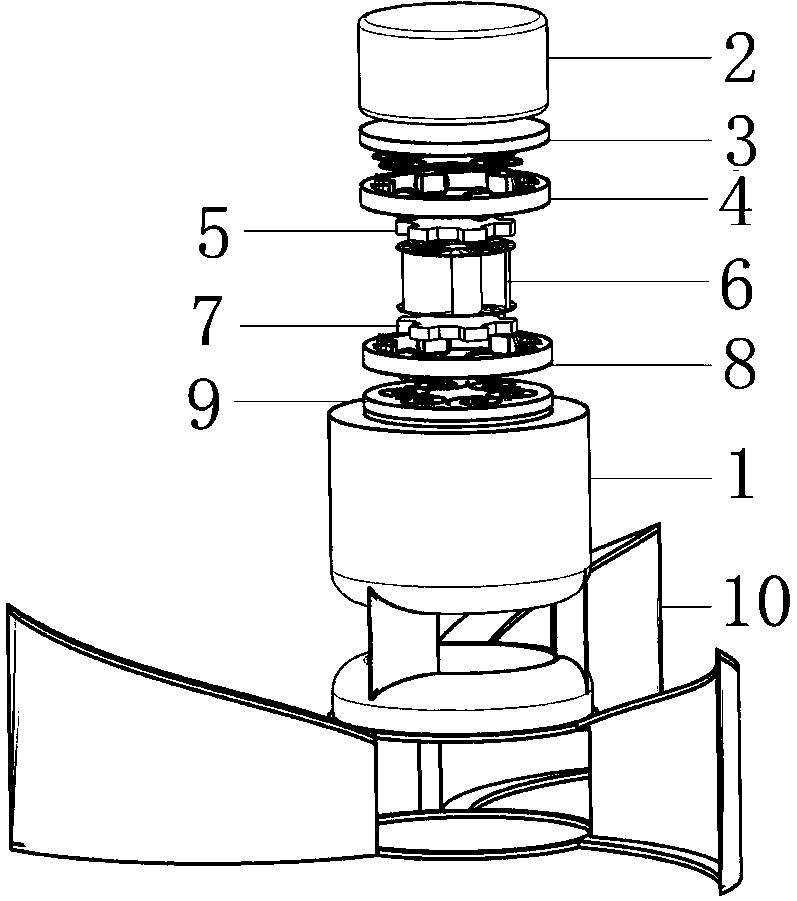
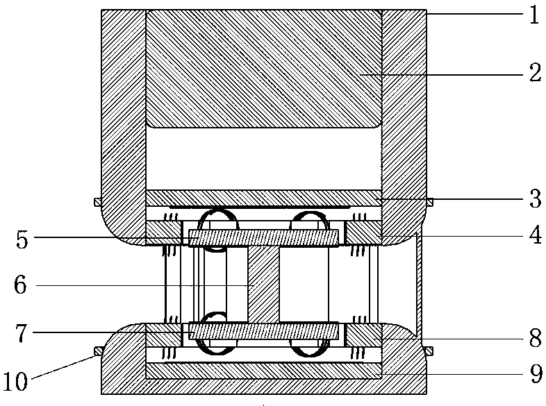
[0024] Such as Figure 1-Figure 5 As shown, an anti-magnetic levitation wind energy harvester includes a housing 1, a permanent magnet 2 installed in the housing, an upper pyrolytic graphite plate 3, an upper stator 4, an upper permanent magnet rotor 5, fan blades 6, and a lower permanent magnet rotor 7. The magnetization directions of the lower stator 8 and the lower pyrolytic graphite plate 9, the permanent magnet 2, the upper permanent magnet rotor 5 and the lower permanent magnet rotor 7 are the same, and the materials of the permanent magnet, the upper permanent magnet rotor and the lower permanent magnet rotor can be magnetic The strongest NdFeB. In order to facilitate assembly, a port can be provided on the top of the shell 1, so that the shell 1 is similar to a barrel-shaped structure. Of course, the shell 1 can also be designed as a structure formed by butting two...


PUM


Abstract

The invention relates to an anti-magnetic levitation wind power energy collector comprising a housing, a permanent magnet arranged in the housing, an upper pyrolytic graphite plate, an upper stator, an upper permanent magnet rotor, a blade, a lower permanent magnet rotor, a lower stator and a lower pyrolytic graphite plate; the upper and lower permanent magnet rotors are respectively fixed on topand bottom ends of the blade so as to be connected to form an integral rotor assembly; a rotor assembly receives a magnetic force of the permanent magnet in the vertical direction and an anti-magneticforce of the lower pyrolytic graphite plate, and receives an anti-magnetic force of the upper pyrolytic graphite plate and the self gravity, wherein the sum of the magnetic force of the permanent magnet in the vertical direction and an anti-magnetic force of the lower pyrolytic graphite plate is equal to the sum of the anti-magnetic force of the upper pyrolytic graphite plate and the self gravity, thus allowing the rotor assembly to suspend between the upper and the lower pyrolytic graphite plates. The collector can greatly reduce the device frictions; in addition, the blade can greatly increase the wind receiving area between the upper permanent magnet rotor and the lower permanent magnet rotor, thus driving the upper permanent magnet rotor and the lower permanent magnet rotor to rotatetogether under a weak wind current, converting weak wind energy in the environment into electric energy, and greatly improving the wind utilization efficiency.

Description

technical field [0001] The invention relates to the field of wind power generators, in particular to an anti-magnetic levitation wind energy collector. Background technique [0002] The principle of wind power generation is to use wind power to drive the generator rotor to rotate to generate electric energy. Wind power generation is a pollution-free and renewable green power. Today, countries all over the world attach importance to energy conservation and environmental protection, and people pay more and more attention to wind power generation. At present, the commonly used wind power generators usually fix the generator on the upper end of the pole or tower through the connecting flange, and directly fix the rotating shaft of the wind blade on the top of the generator. Or it cannot generate electricity when there is a slight wind, and most generators have requirements on the wind direction. During the power generation process, the wind direction needs to be adjusted contin...

Claims


Application Information

Patent Timeline
Patent Type & Authority Applications(China)
IPC IPC(8): F03D9/25
CPCF03D9/25Y02E10/72
Inventor 苏宇锋巩启郭丹武科迪张坤
Owner ZHENGZHOU UNIV
Learn More