Electron beam metal 3D printing device and printing method

A 3D printing and electron beam technology, which is applied in the improvement of process efficiency, additive manufacturing, additive processing, etc., can solve the problem of reducing the processing effect and safety of electron beam 3D printing, reducing the energy of electron beam sintering, and the yield of fine powder. It can improve the real burning power, evenly distribute the metal mass, and enhance the melting effect.

Pending Publication Date: 2019-01-18
JILIN UNIV
View PDF12 Cites 0 Cited by
  • Summary
  • Abstract
  • Description
  • Claims
  • Application Information

AI Technical Summary

Problems solved by technology

However, the existing domestic metal powder particle preparation technology is difficult to prepare high-quality metal powder particles that meet the requirements of electron beam processing, the yield of fine powder is not high, and the cost is relatively high; Some progress has been made in powdering effect, but there are still problems such as thick powder layer, uneven powder spreading, low powder layer density, and low powder spreading efficiency; in the powder spreading process, the powder spreading device, powder spreading The design of the device’s walking mechanism, driving part, and residual material recovery mechanism is relatively complicated, and it takes up a lot of space above the working platform, which reduces the sintering energy of the electron beam to a certain extent; at the same time, because the electron beam processing requires a vacuum and clean processing environment , and it is difficult to avoid the impact of powder particles being blown away and scattered on the processing environment in the process of feeding, powder spreading, processing, and residual material recovery, which greatly reduces the processing effect and safety of electron beam 3D printing
To sum up, for electron beam metal 3D printing, the system and method of additive manufacturing by melting metal powder particles in the past will cause a series of technical problems

Method used


Image

  • Electron beam metal 3D printing device and printing method
  • Electron beam metal 3D printing device and printing method
  • Electron beam metal 3D printing device and printing method

Examples


Embodiment Construction

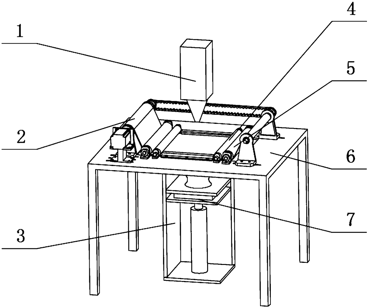
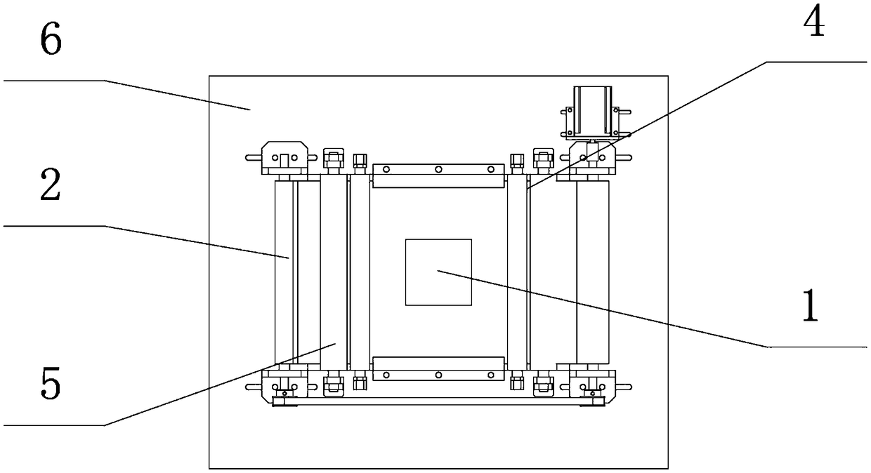
[0036] Such as figure 1 , 2 As shown, it includes the forming chamber 3, the lifting table 7, the working table 6, the electron gun 1, the feeding module 2, the tensioning module 5, and the preheating module 4. The electron gun 1 is located directly above the forming chamber 3 and is kept properly above the working table 6. Distance, the forming room 3 is located under the workbench 6, its square mouth is connected with the workbench square mouth 6-3, the lifting platform 7 that can move up and down is located inside the forming room 3, the feeding module 2 and the tensioning module 5 are respectively connected to the workbench 6 The upper surface is fixedly connected and distributed symmetrically on both sides of the workbench square mouth 6-3. The preheating module 4 is fixedly connected with the upper surface of the workbench 6, which is distributed around the workbench square mouth 6-3.

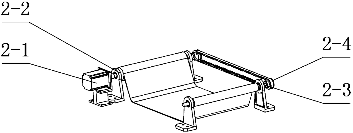
[0037] Such as image 3 As shown, the feeding module 2 is used to realize the transportat...


PUM


Abstract

The invention relates to an electron beam metal 3D printing device and a printing method, and belongs to the field of precision additive manufacturing. An electron gun is located over a forming chamber, the forming chamber is located below a working table, a square opening of the forming chamber is connected with a working table square opening, a lifting platform capable of moving up and down is located in the forming chamber, a feeding module and a tensioning module are fixedly connected with the upper surface of the working table and symmetrically distributed on the two sides of the workingtable square opening, and preheating modules are fixedly connected with the upper surface of the working table and distributed around the working table square opening. The electron beam metal 3D printing device and the printing method have the advantages of achieving the technical purposes of high-quality powder preparation, uniform powder spreading, feeding and recycling, processing environment cleaning and the like, improving the surface quality of formed parts, greatly improving the electron beam processing efficiency, reducing the processing cost and lowering the system control difficulty.

Description

Technical field [0001] The invention belongs to the field of precision additive manufacturing, and particularly relates to an electron beam metal 3D printing device and method for manufacturing high-precision medical implants and high-performance industrial parts. Background technique [0002] Metal 3D printing is a high-end manufacturing technology that realizes parts processing through layer-by-layer material accumulation. It is widely used in aerospace, automotive, mold, medical and other fields, especially in medical implants and industrial high-performance parts. Land demand. At present, metal 3D printing technology is divided into laser 3D printing and electron beam 3D printing according to different heat sources. Compared with laser 3D printing technology, electron beam 3D printing technology has the advantages of higher output power and scanning speed, better preheating effect, better mechanical properties and surface quality of formed parts, so it has a larger applicati...

Claims


Application Information

Patent Timeline
Patent Type & Authority Applications(China)
IPC IPC(8): B22F3/105B33Y30/00B33Y10/00
CPCB33Y10/00B33Y30/00B22F10/00B22F10/28B22F12/13B22F12/50B22F12/30B22F12/224B22F10/73Y02P10/25
Inventor 周晓勤刘赫然刘强郑伟涛何世玉马梦李冬冬
Owner JILIN UNIV
Why Eureka
Try Eureka