
Adaptive Drilling Method Based on Simple Harmonic Vibration Chip Breaking

A simple harmonic vibration and drilling technology, used in metal processing, metal processing equipment, metal processing machinery parts, etc., to achieve the effect of improving processing quality and efficiency

Active Publication Date: 2020-06-09
SHANGHAI JIAOTONG UNIV
View PDF1 Cites 0 Cited by
  • Summary
  • Abstract
  • Description
  • Claims
  • Application Information

AI Technical Summary

Problems solved by technology

However, this type of equipment can only provide one parameter for one-time processing, which is only suitable for single-material drilling, and the parameters need to be changed multiple times for stacked drilling

Method used


Image

  • Adaptive Drilling Method Based on Simple Harmonic Vibration Chip Breaking
  • Adaptive Drilling Method Based on Simple Harmonic Vibration Chip Breaking

Examples


Embodiment Construction

[0018] This embodiment relates to an experimental platform for composite material / alloy laminated automatic drilling equipment, including: a monitoring feedback system, a simple harmonic vibration drilling system and a parameter database system.

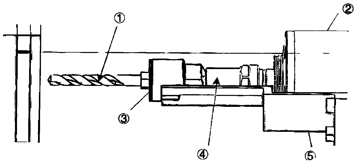
[0019] Such as figure 1 As shown, the simple harmonic vibration drilling system includes: a thread cutter 1, a low-frequency vibration drilling device 3, an adapter 4 and an electric spindle 2 connected in sequence, and the outer side of the electric spindle 2 is further provided with a low-frequency vibration drilling device 3 limit brackets 5 in contact with each other.

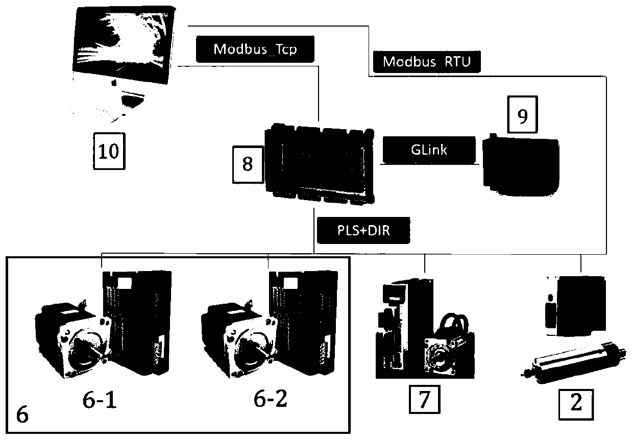
[0020] Such as figure 2 As shown, the monitoring feedback system includes: a motor driver 6 composed of a left and right driver 6-1, an up and down driver 6-2, a feed driver 7, a multi-axis motion control unit 8, a data acquisition unit 9 and an industrial control unit 10, Among them: the industrial control unit 10 is connected with the multi-axis motion contro...


PUM


Abstract

An experimental platform for composite / alloy laminated layer automatic drilling equipment includes monitoring feedback system, a simple harmonic vibration drilling system and a parameter database system. According to the movement condition of a main cutting edge of a drill point, the simple harmonic vibration drilling system establishes a relational graph between the track of the cutting edge andthe thickness of a cutting layer in the processing process, and according to the motion trail of the cutting edge, the real-time cutting layer thickness can be obtained and a feeding-direction cuttingthickness model is obtained at the time of simple harmonic vibration drilling. The model is used for processing a CFRP / Ti laminated layer, performing active simple harmonic vibration chip breaking simulation and outputting a standby processing parameter to the parameter database system, and according to the built-in real-time measured processing parameter and the standby processing parameter, theparameter database system outputs the optimum processing parameter under the matching condition by collecting load power / current data of a servo motor and a motorized spindle in real time. The methodsolves a textual picture of serious damage of titanium alloy chips processed by the CFRP / Ti laminated layer to the pore wall of a CFRP layer, the processing quality is significantly improved, and the method has a very meaningful reference value for processing of a metal laminated layer similar to a composite.

Description

technical field [0001] The present invention relates to a technology in the field of mechanical processing, specifically identifying the change of the drilled material through a certain discriminant algorithm, and automatically changing the drilling processing parameters based on the cutting edge trajectory and the cutting layer thickness curve of the material, so as to realize CFRP / A Machining Method for Stable Chip Breaking During Ti Stack Drilling. Background technique [0002] In the field of aviation industry, C / A laminated members are usually used as load-bearing members. When drilling CFRP / Ti laminated materials, continuous strips of titanium alloy chips will cause serious damage to the hole wall of the CFRP layer. It is difficult to guarantee, and a reasonable chip breaking process is an effective means to solve this problem. In foreign countries, there are already similar automatic feed drilling equipment with embedded low-frequency vibration drilling devices, suc...

Claims


Application Information

Patent Timeline
Patent Type & Authority Patents(China)
IPC IPC(8): B23B35/00B23B41/00B23Q15/12
CPCB23B35/00B23B41/00B23Q15/12
Inventor 陈明密思佩王昌嬴安庆龙
Owner SHANGHAI JIAOTONG UNIV
Learn More