Probe of nuclear magnetic resonance well detecting instrument and nuclear magnetic resonance well detecting instrument

A technology of nuclear magnetic resonance and logging tools, which is applied in the direction of boreholes/well components, earthwork drilling, construction, etc., and can solve problems such as inability to judge formations

Inactive Publication Date: 2019-01-18
CHINA UNIV OF PETROLEUM (BEIJING)
View PDF7 Cites 5 Cited by
  • Summary
  • Abstract
  • Description
  • Claims
  • Application Information

AI Technical Summary

Problems solved by technology

Existing nuclear magnetic resonance logging tools encounter complex and non-uniform formations, partial mud invasion and borehole collapse in many cases. Th

Method used


Image

  • Probe of nuclear magnetic resonance well detecting instrument and nuclear magnetic resonance well detecting instrument
  • Probe of nuclear magnetic resonance well detecting instrument and nuclear magnetic resonance well detecting instrument
  • Probe of nuclear magnetic resonance well detecting instrument and nuclear magnetic resonance well detecting instrument

Examples


Embodiment 1

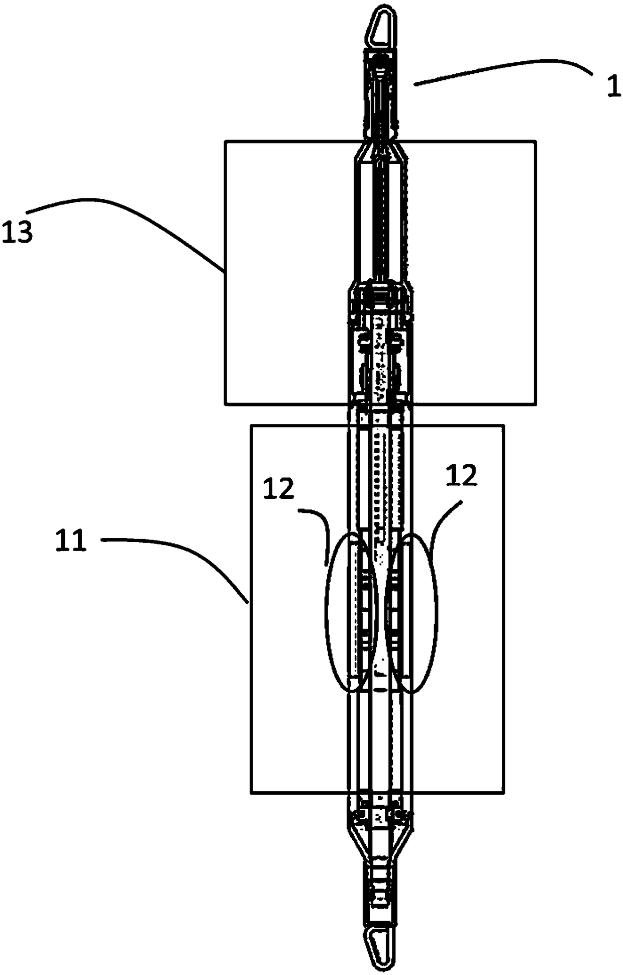
[0052] In Embodiment 1 of the present invention, as figure 1 As shown, the nuclear magnetic resonance logging tool probe 1 includes: a magnet assembly 11 , a coil array 12 and a coil switching control circuit 13 .

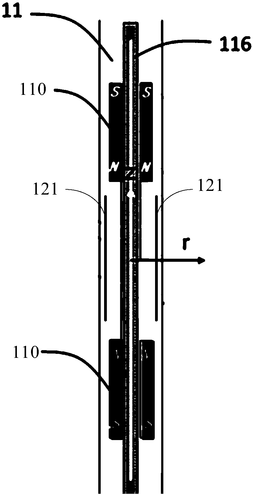
[0053] Such as figure 2 As shown, the magnet assembly 11 includes: a magnet 110 and a support rod 116 , the magnet 110 is fixed on the support rod 116 , and the magnet 110 is used to generate a radially radiating rotationally symmetrical magnetic field.

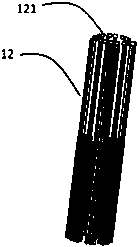
[0054] Such as image 3 As shown, the coil array 12 includes a plurality of identical coils 121 , and the coil array 12 is arranged on the periphery of the magnet assembly 11 at equal intervals along the axial direction. Each coil 121 is used to excite and receive a signal of a sensitive area corresponding to an azimuth angle range, and the signals of the sensitive area corresponding to each coil 121 do not overlap.

[0055] The coil switching control circuit 13 is connected to the coil array 12 , and the coil...

Embodiment 2

[0061] On the basis of the first embodiment above, as Figure 6 As shown, in the nuclear magnetic resonance logging tool probe provided in the second embodiment of the present application, the magnet assembly 11 is a hollow cylinder, and the magnets of the magnet assembly 11 are symmetrical along the radial central axis r, and the radial central axis r is from far to A pair of main magnets 111 , a pair of high magnetic permeability material magnets 114 and a pair of focusing magnets are provided in close order. The pair of focusing magnets may include: a pair of long focusing magnets 113 and a pair of short focusing magnets 112 . A pair of long-focus magnets 113 is close to the radial central axis r, and a pair of short-focus magnets 112 is far away from the radial central axis.

[0062] The magnetization directions of the pair of main magnets 111 are along the axial direction of the magnet assembly 11 and in opposite directions, and the ends of the pair of main magnets 111 w...

Embodiment 3

[0082] Figure 10 The structural schematic diagram of the nuclear magnetic resonance logging instrument provided for the third embodiment of the present invention, such as Figure 10 As shown, the NMR logging tool includes: a transmitter 131 , a receiver 132 and the NMR logging tool probe 1 as in Embodiment 1 and Embodiment 2.

[0083] Wherein, the transmitter 131 and the receiver 132 are respectively connected to the coil switching control circuit 13 of the nuclear magnetic resonance logging tool probe 1 .

[0084] The transmitter 131 is configured to send a switching instruction to the coil switching control circuit 13, and the switching instruction carries a switch coil identification.

[0085] The coil switching control circuit 13 is configured to receive the switching instruction, and switch the coils according to the switching coil identification.

[0086] The receiver 132 is configured to receive the signal of the sensitive area corresponding to the azimuth angle rang...


PUM


Abstract

The invention discloses a nuclear magnetic resonance well detecting instrument probe and a nuclear magnetic resonance well detecting instrument, which comprises a magnet assembly, a coil array and a coil switching control circuit. The magnet assembly comprises a magnet and a support rod, wherein the magnet is fixed on the support rod, and the magnet is used for generating a rotating symmetric magnetic field of radial radiation. The coil array comprises a plurality of identical coils, wherein the coil arrays are arranged evenly at the periphery of the magnet assembly along the axial direction.Each coil can excite and receive signals corresponding to sensitive areas of the azimuth angle range, wherein the signals of sensitive areas corresponding to each coil do not overlap. The coil switching control circuit is connected to the coil array and is used to control the switching of the coils in the coil array. By using the nuclear magnetic resonance well detecting instrument probe and a nuclear magnetic resonance well detecting instrument together, high-resolution underground nuclear magnetic resonance scanning imaging can be realized, so that the user can accurately determine the formation information according to the magnetic resonance scanning imaging result, which is beneficial to the exploitation and development of petroleum reserves.

Description

technical field [0001] The invention relates to the technical field of oil detection, in particular to a nuclear magnetic resonance logging tool probe and a nuclear magnetic resonance logging tool. Background technique [0002] Nuclear Magnetic Resonance (NMR) technology is widely used in physics, chemistry, material science, life science, medicine, oil well measurement and other fields. [0003] Nuclear magnetic resonance logging technology is to use the principle of nuclear magnetic resonance to detect the formation around the borehole. Compared with electrical, acoustic and nuclear radiation logging techniques, the biggest advantage of nuclear magnetic resonance logging is that it only measures the fluid information in the formation, and its signals are not affected by the rock skeleton. It has unique qualitative identification and quantitative identification of reservoir fluids. Evaluate ability. In addition, NMR logging information can also calculate clay-bound water,...

Claims


Application Information

Patent Timeline
IPC IPC(8): E21B47/13E21B49/00
CPCE21B47/13E21B49/00
Inventor 肖立志罗嗣慧汪正垛廖广志李新刘伟孙哲
Owner CHINA UNIV OF PETROLEUM (BEIJING)
Why Eureka
Try Eureka