Dual-fuel engine combustion organization method using high-pressure natural gas injection valve

A dual-fuel engine, natural gas technology, applied in combustion engines, internal combustion piston engines, engine control and other directions, can solve problems such as poor power performance, economical emissions, etc.

Active Publication Date: 2019-01-18
HARBIN ENG UNIV
View PDF9 Cites 4 Cited by
  • Summary
  • Abstract
  • Description
  • Claims
  • Application Information

AI Technical Summary

Problems solved by technology

[0005] The present invention aims at the problem that the above-mentioned dual-fuel engine has relatively poor power performance, economical efficiency and emission performance under different working conditions, and provides a dual-fuel engine combustion organization method using a high-pressure natural gas injection valve

Method used


Image

  • Dual-fuel engine combustion organization method using high-pressure natural gas injection valve
  • Dual-fuel engine combustion organization method using high-pressure natural gas injection valve
  • Dual-fuel engine combustion organization method using high-pressure natural gas injection valve

Examples


Embodiment 1

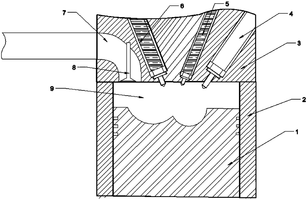
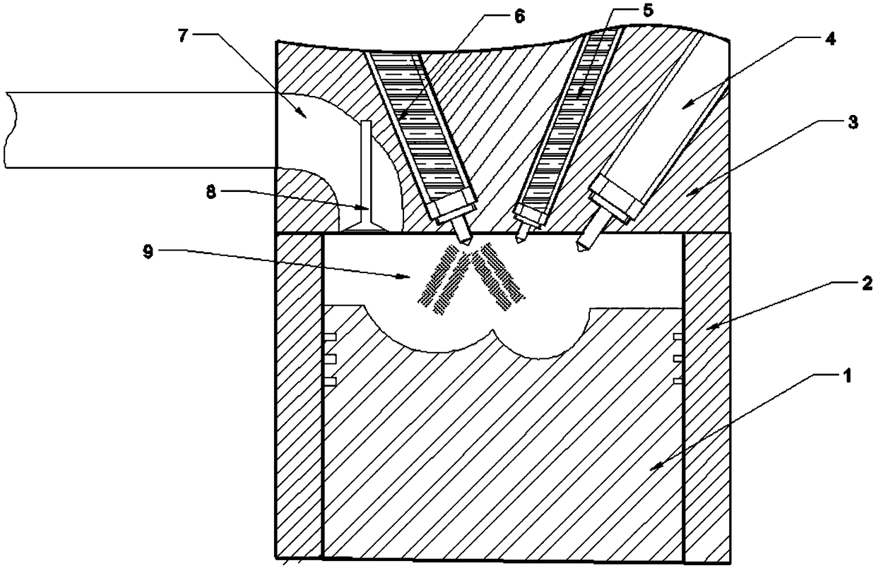
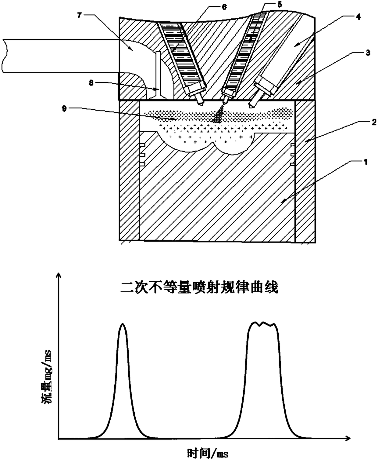
[0022] A dual-fuel engine combustion organization method using high-pressure natural gas injection valves, with four operating modes:

[0023] Mode 1. When the dual-fuel engine starts, the idle speed and the load are lower than 15%, the engine is in the fuel oil operation mode, the high-pressure natural gas injection valve and the auxiliary injector do not work, from the closing of the intake valve to the piston traveling 10- 30°CA, only use the main fuel injector to inject a single injection into the cylinder, because natural gas is prone to misfire due to lean combustion at low load;

[0024] Mode 2. When the dual-fuel engine is at 15-50% low-medium load, the engine is running in gas mode. From the closing of the intake valve to 30°CA before the piston travels to the top dead center, the high-pressure natural gas injection valve performs two non-stop injections to the combustion chamber. Equal amount of natural gas injection, at the same time when the piston travels to 15-25...

Embodiment example 2

[0031] The invention belongs to the field of internal combustion engine combustion methods, and in particular relates to a dual-fuel engine combustion organization method and a combustion system composition using main and auxiliary injectors and high-pressure multiple injections in a natural gas cylinder.

[0032] Compared with other types of engines, dual-fuel engines have obvious advantages in terms of economy of use, thermal efficiency, combustion noise, NOx and PM emissions, etc.; Knocking is prone to occur under load, the increase of natural gas substitution rate is limited, and there are problems such as high HC and CO emissions.


PUM


Abstract

The invention provides a dual-fuel engine combustion organization method using a high-pressure natural gas injection valve. When the load of a dual-fuel engine is less than 15%, a main fuel injector performs a single injection into a cylinder. When the load of the dual-fuel engine is 15 to 50%, the high-pressure natural gas injection valve performs two unequal amounts of injections into a combustion chamber, and a secondary fuel injector performs a micro single injection. When the load of the dual-fuel engine is 50 to 75%, two equal amounts of natural gas injections are performed, and the secondary fuel injector performs a micro single injection. When the load of the dual-fuel engine is greater than 75%, a single natural gas injection is performed, and the secondary fuel injector performsa micro single injection. According to the working condition of the dual-fuel engine, by adjusting the injection timing, the number of injections and the injection quantity of the high-pressure natural gas injection valve, the concentration gradient distribution of a mixed gas in the cylinder is controlled to realize stratified combustion and homogeneous combustion. The injection timing of the main and secondary fuel injects are adjusted to control the starting point of combustion, in order that the fuel concentration distribution of the dual-fuel engine is in the optimal state under various working conditions, which is beneficial to the stabile, high-efficient and low-emission combustion of the engine.

Description

technical field [0001] The invention belongs to the field of internal combustion engine combustion methods, and in particular relates to a dual-fuel engine combustion organization method using a high-pressure natural gas injection valve. Background technique [0002] Compared with other types of engines, dual-fuel engines have obvious advantages in terms of economy of use, thermal efficiency, combustion noise, NOx and PM emissions, etc.; Knocking is prone to occur under load, the increase of natural gas substitution rate is limited, and there are problems such as high HC and CO emissions. [0003] In terms of optimizing the combustion system, patent CN102996223A achieves homogeneous premixed compression ignition by injecting fuels with different octane numbers through the main and auxiliary nozzles, which ensures high thermal efficiency; patent CN106870186A summarizes the possible fuel injection methods for dual-fuel engines, Different combustion modes are realized through ...

Claims


Application Information

Patent Timeline
Patent Type & Authority Applications(China)
IPC IPC(8): F02D19/06F02D19/08
CPCF02D19/0647F02D19/0689F02D19/0692F02D19/0694F02D19/081Y02T10/30
Inventor 杨立平包军杰宋恩哲范立云董全
Owner HARBIN ENG UNIV
Why Eureka
Try Eureka