A self-balancing pressure regulating valve pressure regulating hydraulic system and its control method

A technology of hydraulic system and pressure regulating valve, which is applied in the direction of fluid pressure actuation system components, valve operation/release device, valve device, etc., which can solve the problem of low economy and efficiency of test operation, prolonged test preparation time, and waste of gas source and other problems, to achieve the effect of convenient control, simple and reliable operation, and small footprint

Active Publication Date: 2019-12-20
BEIJING AEROSPACE YISEN WIND TUNNEL ENG TECH
View PDF7 Cites 0 Cited by
  • Summary
  • Abstract
  • Description
  • Claims
  • Application Information

AI Technical Summary

Problems solved by technology

[0005] The embodiment of the present invention provides a self-balancing pressure regulating valve pressure regulating hydraulic system and its control method, in order to solve the need to manually adjust the oil supply pressure of the hydraulic station with a tool such as a wrench in the prior art, which is inconvenient and Inaccurate, waste gas source and prolong the test preparation time, the economy and efficiency of the test operation are extremely low

Method used


Image

  • A self-balancing pressure regulating valve pressure regulating hydraulic system and its control method
  • A self-balancing pressure regulating valve pressure regulating hydraulic system and its control method

Examples


Embodiment 1

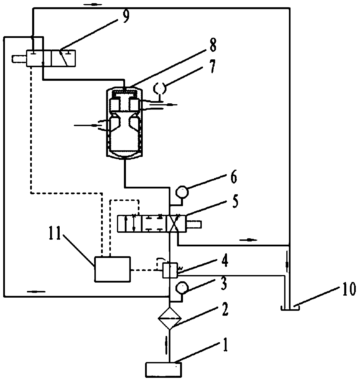
[0026] refer to figure 1 , shows a structural schematic diagram of a pressure regulating hydraulic system of a self-balancing pressure regulating valve provided by an embodiment of the present invention.

[0027] Such as figure 1 As shown, the pressure regulating hydraulic system of the self-balancing pressure regulating valve may include: hydraulic station 1, electro-hydraulic proportional pressure reducing valve 4, electro-hydraulic servo valve 5, self-balancing pressure regulating valve 8, electromagnetic reversing valve 9, programmable logic Controller 11 and fuel tank 10.

[0028] The connection relationship of each part in the pressure regulating hydraulic system is as follows:

[0029] Such as figure 1 As shown, one end of the hydraulic station 1 is connected to one end of the electro-hydraulic proportional pressure reducing valve 4, the other end of the electro-hydraulic proportional pressure reducing valve 4 is connected to one end of the electro-hydraulic servo va...

Embodiment 2

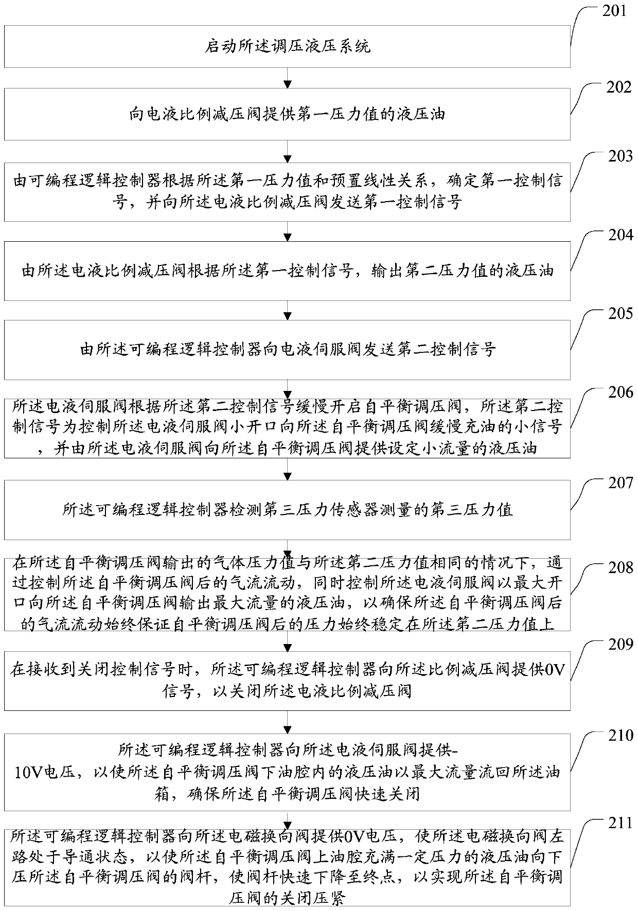
[0051] refer to figure 2 , shows a flow chart of the steps of a self-balancing pressure regulating valve pressure regulating control method provided by an embodiment of the present invention, the self-balancing pressure regulating valve pressure regulating control method can be applied to any one of the first embodiment above The pressure regulating hydraulic system described above may specifically include the following steps:

[0052] Step 201: Start the pressure regulating hydraulic system.

[0053] The embodiments of the present invention can be applied to the scene of rapid and accurate pressure regulation of a self-balancing pressure regulating valve of high-pressure airflow in a hypersonic wind tunnel.


PUM


Abstract

The invention provides a pressure regulating hydraulic system for a self-balancing pressure regulating valve and a control method thereof. The pressure regulating hydraulic system is characterized inthat a hydraulic station supplies a hydraulic oil source of a first set pressure value; an electro-hydraulic ratio decompression valve outputs hydraulic oil of a second set pressure value according toa first control signal on the basis of the set proportional relation; an electro-hydraulic servo valve outputs hydraulic oil to the self-balancing pressure regulating valve according to a second control signal on the basis of the opening magnitude, and controls the self-balancing pressure regulating valve to be turned on or turned off according to the opening direction; the self-balancing pressure regulating valve controls the first pressure value of the hydraulic oil entering the self-balancing pressure regulating valve and the second pressure value of gas output by the self-balancing pressure regulating valve to be consistent; an electromagnetic reversing valve controls the self-balancing pressure regulating valve to be turned off and compressed or decompressed and turned on according to a third control signal; a programmable logic controller outputs a first control signal to the electro-hydraulic ratio decompression valve, outputs a second control signal to the electro-hydraulic servo valve, and outputs a third control signal to the electromagnetic reversing valve; an oil tank stores an oil source. Gas pressure control is convenient and accurate.

Description

technical field [0001] The invention relates to the field of driving and control of a high-pressure air pressure regulating valve, in particular to a pressure regulating hydraulic system of a self-balancing pressure regulating valve and a control method thereof. Background technique [0002] Conventional hypersonic wind tunnel operation requires a certain amount of high-pressure gas. The high-pressure gas is generally stored in a high-pressure tank in advance. With the operation of the wind tunnel, the amount of high-pressure gas used increases cumulatively, and the gas pressure in the tank gradually decreases. When the pressure drops to a certain After the pressure value is exceeded, the test operating conditions are no longer met and the test must be terminated. In a test, the longer the operation time, the greater the gas consumption and the higher the operating cost. In the case of ensuring a certain effective running time, reducing the air consumption while making the ...

Claims


Application Information

Patent Timeline
Patent Type & Authority Patents(China)
IPC IPC(8): F16K31/12F15B21/08F15B11/08F15B13/04
CPCF15B11/08F15B13/0401F15B21/087F16K31/12
Inventor 李玉秋程益恒康永泰陈良泽
Owner BEIJING AEROSPACE YISEN WIND TUNNEL ENG TECH
Why Eureka
Try Eureka