A heat dissipation magnetic insulation tape and a wireless charging power receiver

A power receiver and power receiving technology, applied in the direction of current collectors, battery circuit devices, power electronics modification, etc., can solve the problems of low charging efficiency and large heat generation of wireless chargers

Active Publication Date: 2019-01-18
SHENZHEN MEIXIN ELECTRONICS +1
View PDF9 Cites 14 Cited by
  • Summary
  • Abstract
  • Description
  • Claims
  • Application Information

AI Technical Summary

Problems solved by technology

[0004] However, wireless chargers have defects such as low charging efficiency and high heat generation during charging.

Method used


Image

  • A heat dissipation magnetic insulation tape and a wireless charging power receiver
  • A heat dissipation magnetic insulation tape and a wireless charging power receiver
  • A heat dissipation magnetic insulation tape and a wireless charging power receiver

Examples


Embodiment 1

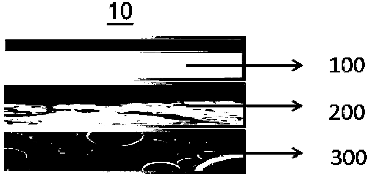
[0038] This embodiment provides a heat dissipation magnetic isolation tape 10, referring to figure 1 As shown, it includes an insulating and protective adhesive layer 100 , a composite heat dissipation adhesive layer 200 , and a magnetic isolation adhesive layer 300 that are stacked. Wherein, the composite heat dissipation adhesive layer 200 is located between the insulating and protective adhesive layer 100 and the magnetic isolation adhesive layer 300 .

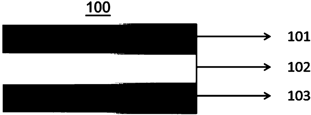
[0039] like figure 2 As shown, the insulating and protective adhesive layer 100 includes an insulating layer 102 , and a first pressure-sensitive adhesive layer 103 is provided on the side of the insulating layer 102 facing the composite heat dissipation adhesive layer 200 . The insulation layer 102 mainly plays the role of insulation protection, and its material can be PET film or PI film. The first pressure-sensitive adhesive layer 103 is used to bond the insulating layer 102 to the composite heat dissipation adhesive ...

Embodiment 2

[0056] This embodiment provides a heat dissipation magnetic isolation tape, which has a layered structure similar to the heat dissipation magnetic isolation tape 10 provided in Example 1, which includes an insulating and protective adhesive layer, a composite heat dissipation adhesive layer and a magnetic isolation adhesive Floor.

[0057] The insulating protective adhesive layer uses a PET film with a thickness of 2 μm as the insulating layer, and the side of the insulating layer away from the composite heat dissipation adhesive layer is coated with a matte black ink layer with a thickness of 1 μm, and the insulating layer is far away from the side of the composite heat dissipation adhesive layer Coated with a first pressure-sensitive adhesive layer with a thickness of 2 μm.

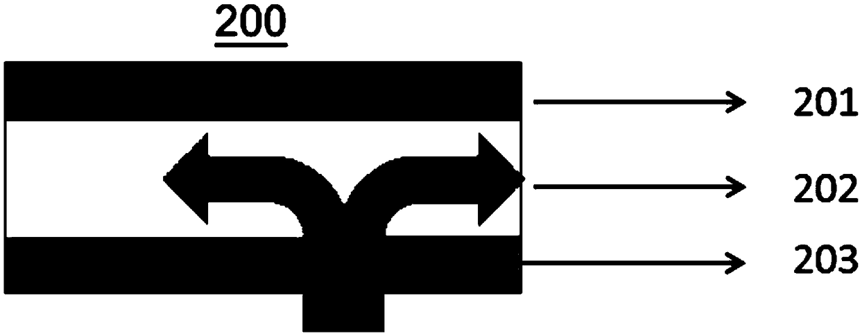
[0058] The composite heat dissipation adhesive layer uses copper foil with a thickness of 9 μm as the metal foil, and the side of the metal foil facing the insulating and protective adhesive layer is co...

Embodiment 3

[0061] This embodiment provides a heat dissipation magnetic isolation tape, which has a layered structure similar to the heat dissipation magnetic isolation tape 10 provided in Example 1, which includes an insulating and protective adhesive layer, a composite heat dissipation adhesive layer and a magnetic isolation adhesive Floor.

[0062] The insulation protection adhesive layer uses a PET film with a thickness of 8 μm as the insulating layer, and the side of the insulating layer away from the composite heat dissipation adhesive layer is coated with a matte black ink layer with a thickness of 4 μm, and the insulating layer is far away from the side of the composite heat dissipation adhesive layer Coated with a first pressure-sensitive adhesive layer with a thickness of 8 μm.

[0063] The composite heat dissipation adhesive layer uses copper foil with a thickness of 20 μm as the metal foil. The side of the metal foil facing the insulating and protective adhesive layer is coate...


PUM

PropertyMeasurementUnit
thicknessaaaaaaaaaa
thicknessaaaaaaaaaa
thicknessaaaaaaaaaa

Abstract

A heat dissipation magnetic insulation tape includes an insulating protective adhesive layer, a composite heat dissipation adhesive layer, and a magnetic insulation adhesive layer which are stacked. the composite heat dissipation adhesive layer is made of thin metal foil coated with heat dissipation graphene, which has good thermal diffusion performance. At the same time, compared with the traditional graphite sheet, the metal foil is not fragile, and no fragments will enter the equipment body. In addition, the metal foil also has excellent electromagnetic shielding function. The heat dissipation and magnetic insulation tape has the characteristics of excellent magnetic insulation effect, good heat dissipation performance and stable adhesion. A wireless charging power receiver includes theheat dissipation magnetic isolation tape, which is thin in thickness, excellent in heat dissipation magnetic isolation performance, stable in adhesion performance, and has high charging efficiency.

Description

technical field [0001] The invention relates to the field of wireless charging, in particular to a heat dissipation and magnetic isolation tape and a wireless charging power receiver. Background technique [0002] Wireless charging technology uses the principle of electromagnetic induction, that is, changes in the surrounding magnetic field will cause current to be generated in the wire. In the 1890s, scientist Nikola Tesla demonstrated the possibility of wirelessly transmitting radio waves and filed the first patent. At present, there are four different commercial technologies for wireless charging: electromagnetic induction technology, radio wave technology and electromagnetic resonance technology, and electric field coupling technology. [0003] Several technologies have their own characteristics. Now the wireless charging technology in large-scale mass production is electromagnetic induction technology. In electromagnetic induction technology, the charging base (transmi...

Claims


Application Information

Patent Timeline
Patent Type & Authority Applications(China)
IPC IPC(8): H02J50/10H02J50/70H02J7/00H05K7/20
CPCH02J7/025H02J50/10H02J50/70H05K7/2089H05K7/20909
Inventor 陈维斌林学好
Owner SHENZHEN MEIXIN ELECTRONICS
Why Eureka
Try Eureka