Accumulator type electronic control fuel injection system with variable supercharge ratio

A technology of fuel injection system and supercharging ratio, which is applied to fuel injection devices, charging systems, engine components, etc., can solve the problems of difficult flexible control of fuel injection rate, decrease of uniformity and stability of fuel injection process, etc. Achieve the effect of improving economy and power, and improving flexibility

Inactive Publication Date: 2019-01-22
HARBIN ENG UNIV
View PDF4 Cites 5 Cited by
  • Summary
  • Abstract
  • Description
  • Claims
  • Application Information

AI Technical Summary

Problems solved by technology

However, the existing pressurized electronically controlled fuel injector is restricted by the structure of the booster piston. For a certain common rail pressure, after the booster piston amplifies the fuel pressure in a certain proportion, the system can only inject fuel at a certain certain rate. It is difficult to realize flexible control of fuel injection pressure and fuel injection rate of diesel engine under different working conditions
Secondly, in the state of large fuel injection, the uniformity and stability of the fuel injection process of each cylinder is reduced

Method used


Image

  • Accumulator type electronic control fuel injection system with variable supercharge ratio
  • Accumulator type electronic control fuel injection system with variable supercharge ratio
  • Accumulator type electronic control fuel injection system with variable supercharge ratio

Examples


Embodiment Construction

[0023] The present invention is described in more detail below in conjunction with accompanying drawing example:

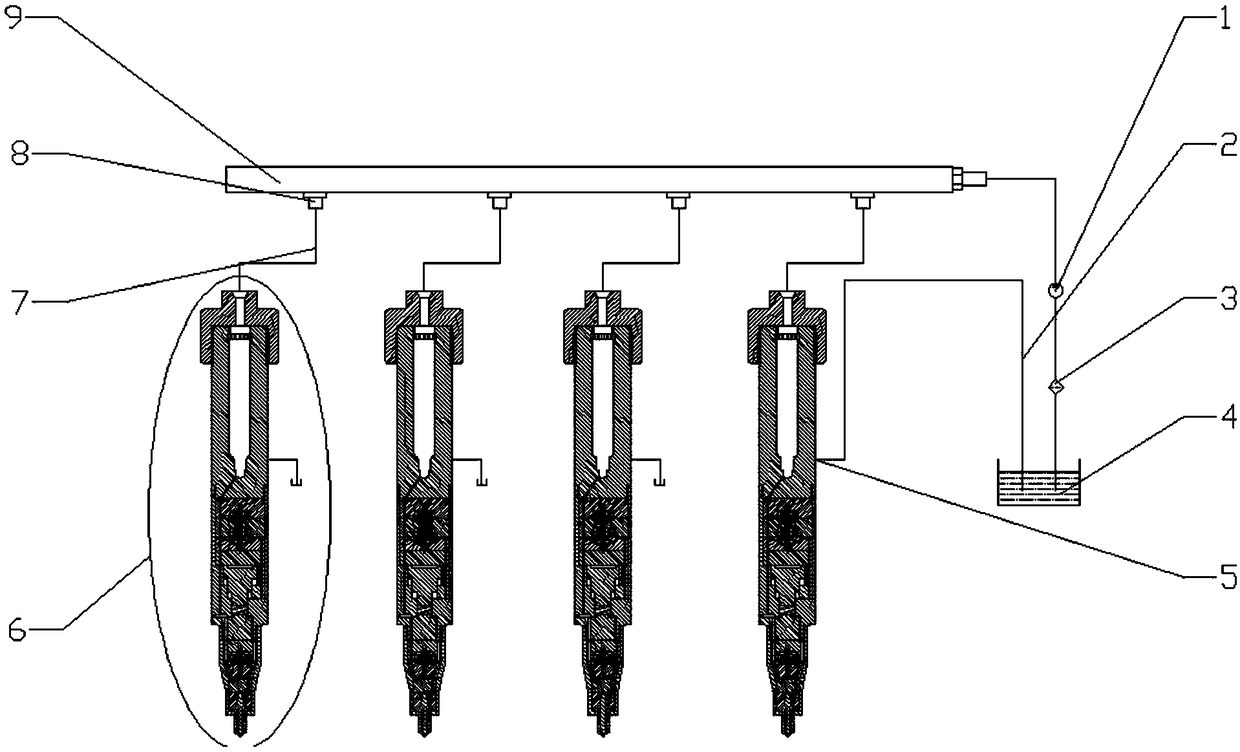
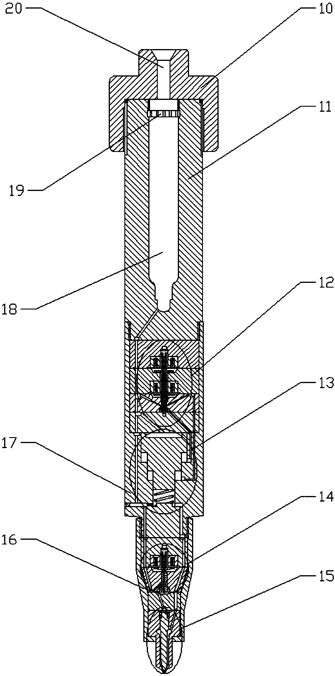
[0024] combine Figure 1-6 , the variable boost ratio accumulator pressure electronically controlled fuel injection system of the present invention comprises a common rail pipe 9, a high pressure oil pipe 7, a high pressure oil pump 1, a filter 3, a fuel tank 4, an oil return pipe 2 and a fuel injector 6, and the common rail pipe The right end of 9 is connected with high-pressure oil pump 1, filter 3 and oil tank 4 respectively. There are multiple hydraulic oil outlets 8 on the common rail pipe 9. The number of hydraulic oil outlets 8 is determined according to the number of cylinders of the internal combustion engine. The oil pipe 7 communicates with the fuel inlet 20 opened on the fuel injector 6 , and the low-pressure fuel return port 5 opened on the fuel injector 6 communicates with the fuel tank 4 through the oil return pipe 2 . The fuel injector 6 is compos...


PUM


Abstract

The purpose is to provide an accumulator type electronic control fuel injection system with the variable supercharge ratio. The system comprises a common rail pipe, a high-pressure oil pipe, a high-pressure oil pump, a filter, an oil tank, an oil return pipe and an oil atomizer. A second-level electromagnetic valve structure is adopted, a pressurizing area of a three-level piston is controlled, different supercharge ratios can be effectively achieved, and the oil injection law can be more flexible; the motion process of a needle valve is firstly driven by a guide type electromagnetic valve, the responding speed of the needle valve is high, the control freedom degree is large, the oil injection law is flexible and controllable, the dynamic property of a diesel engine and the economical efficiency of fuel are effectively improved, and the diesel engine can meet more strict emission regulations; a pressurizing control valve and an oil injecting control valve are soaked in low-pressure oil, which has a cooling effect on the electromagnetic valve, and safe and reliable work is ensured; a hole plate structure is arranged in a pressure storage cavity, fluctuation of pressure of fuel in the oil atomizer is reduced, fluctuation of circular fuel-injection quantity is reduced, and the multi-time injecting process of a high-pressure common rail fuel system is further controlled more accurately.

Description

technical field [0001] The invention relates to a diesel engine, in particular to a diesel engine fuel system. Background technique [0002] The fuel injection system of a diesel engine is the core component of a diesel engine, and the quality of the combustion process of a diesel engine largely depends on the performance of the fuel injection system. The guiding principle for organizing the ideal combustion process of a diesel engine is to suppress initial combustion, accelerate mid-term combustion, and reduce afterburning. This requires that the fuel injection rate of the electronically controlled injector should be low first and then high, the end of fuel injection should be quick, and the duration of fuel injection should be moderate. However, for the existing electronically controlled fuel injection system, realizing the above injection process will greatly increase the difficulty of control. [0003] Due to the large cycle fuel injection volume of large and medium-siz...

Claims


Application Information

Patent Timeline
Patent Type & Authority Applications(China)
IPC IPC(8): F02M55/02F02M47/02F02M51/06F02M61/10F02M61/16F02M61/18F02M63/00
CPCF02M47/027F02M51/061F02M55/025F02M61/10F02M61/16F02M61/18F02M63/0017
Inventor 范立云付立洲白云
Owner HARBIN ENG UNIV
Why Eureka
Try Eureka