
A broadband channelized transceiver

A transceiver and channelization technology, applied in electrical components, transmission systems, etc., can solve the problems of low sampling frequency, low circuit utilization, complicated design, etc., and achieve high transceiver isolation, high-speed transceiver processing, and wide operating frequency band. Effect

Active Publication Date: 2019-01-22
HUBEI SANJIANG SPACE XIANFENG ELECTRONICS&INFORMATION CO LTD
View PDF5 Cites 8 Cited by
  • Summary
  • Abstract
  • Description
  • Claims
  • Application Information

AI Technical Summary

Problems solved by technology

However, the working bandwidth of DRFM is limited by the sampling frequency of AD / DA devices. The sampling frequency of commonly used high-performance AD / DA devices is generally not high enough to meet the requirements of the wide operating frequency band of the whole machine; the cost price of AD / DA devices with ultra-high sampling frequency Higher, lower cost performance, fewer applications
In order to meet the broadband working requirements of digital radio frequency memory (DRFM), there are two methods currently used: 1. Single broadband channel, using frequency hopping local oscillator, but there is a problem of long response time for sending and receiving, and the clutter of the transmitted signal is relatively large. Many; 2. Multiple narrowband transceiver channels jointly cover a broadband working frequency band, but there are disadvantages of low circuit utilization, complex design, and relatively high cost

Method used


Image

  • A broadband channelized transceiver

Examples


Embodiment Construction

[0027] In order to make the objectives, technical solutions and advantages of the present invention clearer, the following further describes the present invention in detail with reference to the accompanying drawings and embodiments. It should be understood that the specific embodiments described herein are only used to explain the present invention, but not to limit the present invention.

[0028] In addition, the technical features involved in the various embodiments of the present invention described below can be combined with each other as long as they do not conflict with each other. The present invention will be further described in detail below in conjunction with specific embodiments.

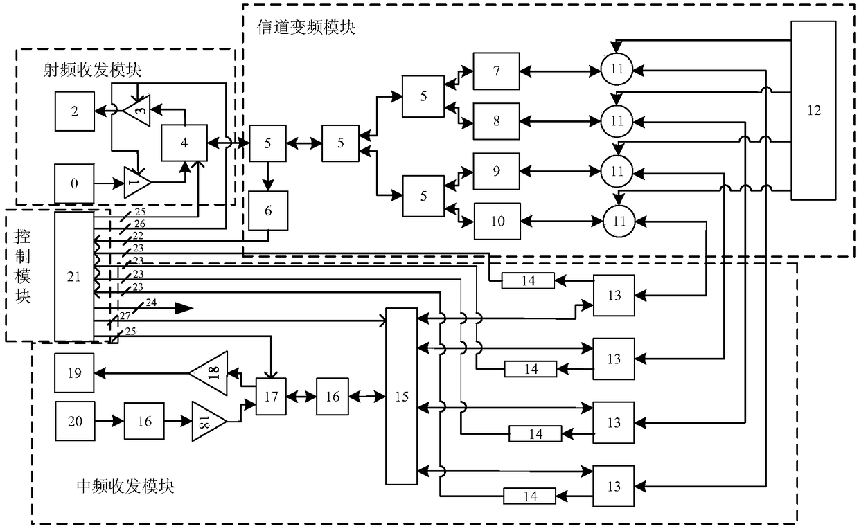
[0029] figure 1 It is a schematic structural diagram of a broadband channelized transceiver device according to a preferred embodiment of the present invention. Such as figure 1 As shown in the figure, the device includes a radio frequency transceiver module, a channel frequency conversio...


PUM


Abstract

The invention discloses a broadband channelized transceiver which comprises a radio frequency transceiver module, a channel frequency conversion module, an intermediate frequency transceiver module and a control module.The device utilizes the radio frequency transceiver module, the channel frequency conversion module, the intermediate frequency transceiver module and the control module which are sequentially connected.When receiving the signal, the radio frequency signal received by the radio frequency transceiver module is divided into radio frequency signals of different working frequency bands by the channel frequency conversion module and is mixed and sentto the intermediate frequency transceiver module;and an effective intermediate frequency geophone channel is judged by a control module according to a detection signal sent by a plurality of intermediate frequency geophones and a preset threshold value, at the same time, corresponding control signals are generated for SPMT IF switches. The IF transceiver module controls the opening and closing of SPMT IF switch according to the control signal of the control module to realize the signal input or output of the corresponding IF power divider, and realizes the signal transceiver mode of wideband RF input, narrowband IF output, narrowband IF input and wideband RF output.

Description

Technical field [0001] The invention belongs to the field of antenna microwave radio frequency, and specifically relates to a broadband channelized transceiver device. Background technique [0002] In electronic countermeasures equipment, digital radio frequency memory (DRFM) is a microwave signal storage system used to store and forward radio frequency signals. The digital radio frequency memory performs high-speed sampling, storage, conversion processing and reconstruction of the radio frequency signal received by the antenna to achieve high-speed signal capture and storage, diversity of interference technologies, and flexibility of control. As an interference device, digital radio frequency memory has become a key component of the electronic countermeasure system. [0003] In electronic countermeasures equipment, especially for interfering equipment using digital radio frequency memory (DRFM), it is often required to have an extremely wide operating frequency range. However, t...

Claims


Application Information

Patent Timeline
IPC IPC(8): H04B1/401
CPCH04B1/401
Inventor 万奇龙邱世锋高天阳
Owner HUBEI SANJIANG SPACE XIANFENG ELECTRONICS&INFORMATION CO LTD
Learn More