Dual-wavelength good-and-bad-cavity active optical clock based on secondary cavity locking technology, and implementation method thereof

A dual-wavelength, active light technology, applied in lasers, laser parts, instruments using atomic clocks, etc., can solve the problems of the use of optical frequency standards, the failure to give full play to the advantages of active optical clocks, and the inability to further narrow the output laser line width.

Active Publication Date: 2019-01-25
PEKING UNIV
View PDF3 Cites 16 Cited by
  • Summary
  • Abstract
  • Description
  • Claims
  • Application Information

AI Technical Summary

Problems solved by technology

[0005] At present, the four-level active optical clock realized by thermal atoms has proved that the cavity pulling effect can be effectively suppressed, thereby reducing the influence of cavity length thermal noise on the output laser frequency, but because the active optical clock resonator (main resonator) is not locked ) cavity leng...

Method used


Image

  • Dual-wavelength good-and-bad-cavity active optical clock based on secondary cavity locking technology, and implementation method thereof
  • Dual-wavelength good-and-bad-cavity active optical clock based on secondary cavity locking technology, and implementation method thereof

Examples


Embodiment 1

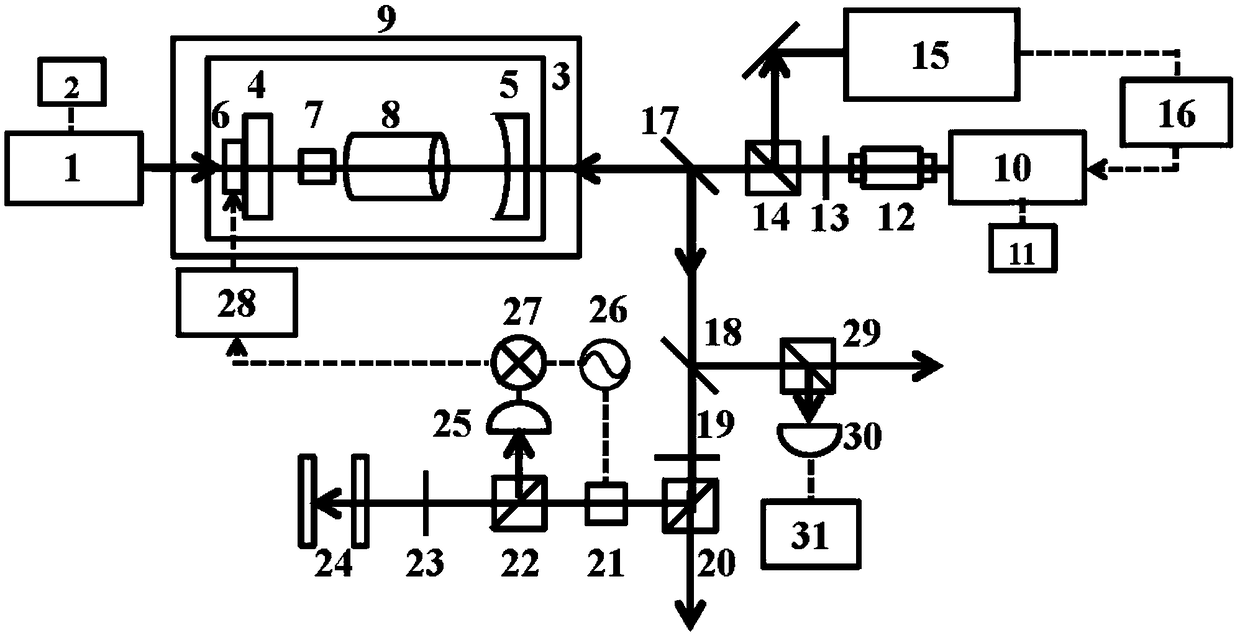
[0041] Such as figure 1 As shown, the dual-wavelength good-and-bad-cavity active optical clock based on the secondary cavity-locking technology of this embodiment and its implementation method include: a first laser 1, a first laser power supply 2, an integrated Invar resonant cavity body 3, four Point-coated main resonant cavity mirror-plane mirror 4 and plano-concave mirror 5, piezoelectric ceramic sheet 6, good cavity laser gain medium 7, alkali metal atomic gas cell 8, magnetic shielding box 9, second laser 10, second laser Power supply 11, isolator 12, first half-wave plate 13, first polarization beam splitter prism 14, modulation transfer spectrum frequency stabilization module 15, first servo feedback circuit 16, first dichroic mirror 17, second dichroic mirror 18, second Half wave plate 19, second polarization beam splitter 20, phase modulator 21, third polarization beam splitter 22, quarter wave plate 23, high-precision Fabry-Perot reference cavity 24, first photodete...

Embodiment 2

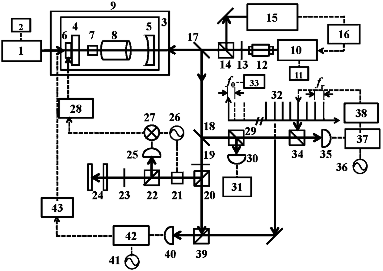
[0049] Such as figure 2 As shown, the dual-wavelength good-and-bad-cavity active optical clock and its implementation method based on the secondary lock cavity technology of the present invention include: all optical elements and instruments used in Embodiment 1, ultra-stable femtosecond optical frequency comb 32, microwave atomic clock 33. The fifth polarization beam splitter prism 34, the third photodetector 35, the second signal generator 36, the first phase-locked loop 37, the third servo feedback circuit 38, the sixth polarization beam splitter prism 39, the fourth photodetector 40 , a third signal generator 41 , a second phase-locked loop 42 , and a fourth servo feedback circuit 43 .

[0050] 1) The wavelength range of the optical comb should cover 1000-1500nm, where the zero frequency f ceo The signal is locked on the frequency reference provided by the microwave atomic clock: 1f-2f interference (self-referencing technique) is used to extract the zero frequency f of t...


PUM


Abstract

The invention discloses a dual-wavelength good-and-bad-cavity active optical clock based on the secondary cavity locking technology, and an implementation method thereof. The dual-wavelength good-and-bad-cavity active optical clock and the implementation method thereof have the advantages that a solution based on the secondary cavity locking technology is provided, the cavity traction suppressioneffect of bad cavity lasers in a dual-wavelength good-and-bad-cavity laser system is utilized twice, the influences of the residual cavity traction effect on the long-term stability of an active optical frequency standard are eliminated, the cavity traction suppression effect is amplified to squared times of the bad cavity coefficient of a main resonant cavity, the length of the main resonant cavity is locked twice by a servo feedback system, and the immunity of the active optical frequency standard in the dual-wavelength good-and-bad-cavity system to cavity mold jittering is achieved.

Description

technical field [0001] The invention belongs to the technical field of atomic clocks and frequency standards, and in particular relates to a dual-wavelength active optical clock based on secondary lock cavity technology and a realization method thereof. Background technique [0002] Precise time and frequency standards, namely atomic clocks, have important applications in precision measurement, information network time synchronization, international standard time coordination, global navigation and positioning systems, etc. Therefore, in the field of metrology, atomic clocks have always been one of the key research directions. Especially in the past ten years, the field of optical frequency metrology has developed rapidly. At present, the performance of optical frequency atomic clocks has surpassed microwave atomic clocks. The stability and accuracy of optical frequency atomic clocks (optical clocks) realized by optical lattice and single ion trapping technology degree has r...

Claims


Application Information

Patent Timeline
IPC IPC(8): G04F5/14H01S3/136
CPCG04F5/14H01S3/136
Inventor 陈景标史田田潘多
Owner PEKING UNIV
Why Eureka
Try Eureka