
Equipment and process for weaving composite material

A composite material and equipment technology, applied in the direction of woven fabrics, textiles and papermaking, etc., can solve the problems of heavy insulating operating rod, poor insulating performance, low fiber density, etc., and achieve the effect of thick woven layer, less internal bubbles, and more types

Pending Publication Date: 2019-01-29
STATE GRID CORP OF CHINA +3
View PDF4 Cites 7 Cited by
  • Summary
  • Abstract
  • Description
  • Claims
  • Application Information

AI Technical Summary

Problems solved by technology

[0004] In view of this, the present invention proposes an equipment and process for weaving composite materials, aiming to solve the existing problems of heavy insulating operating rods, low fiber density, and poor insulating performance

Method used

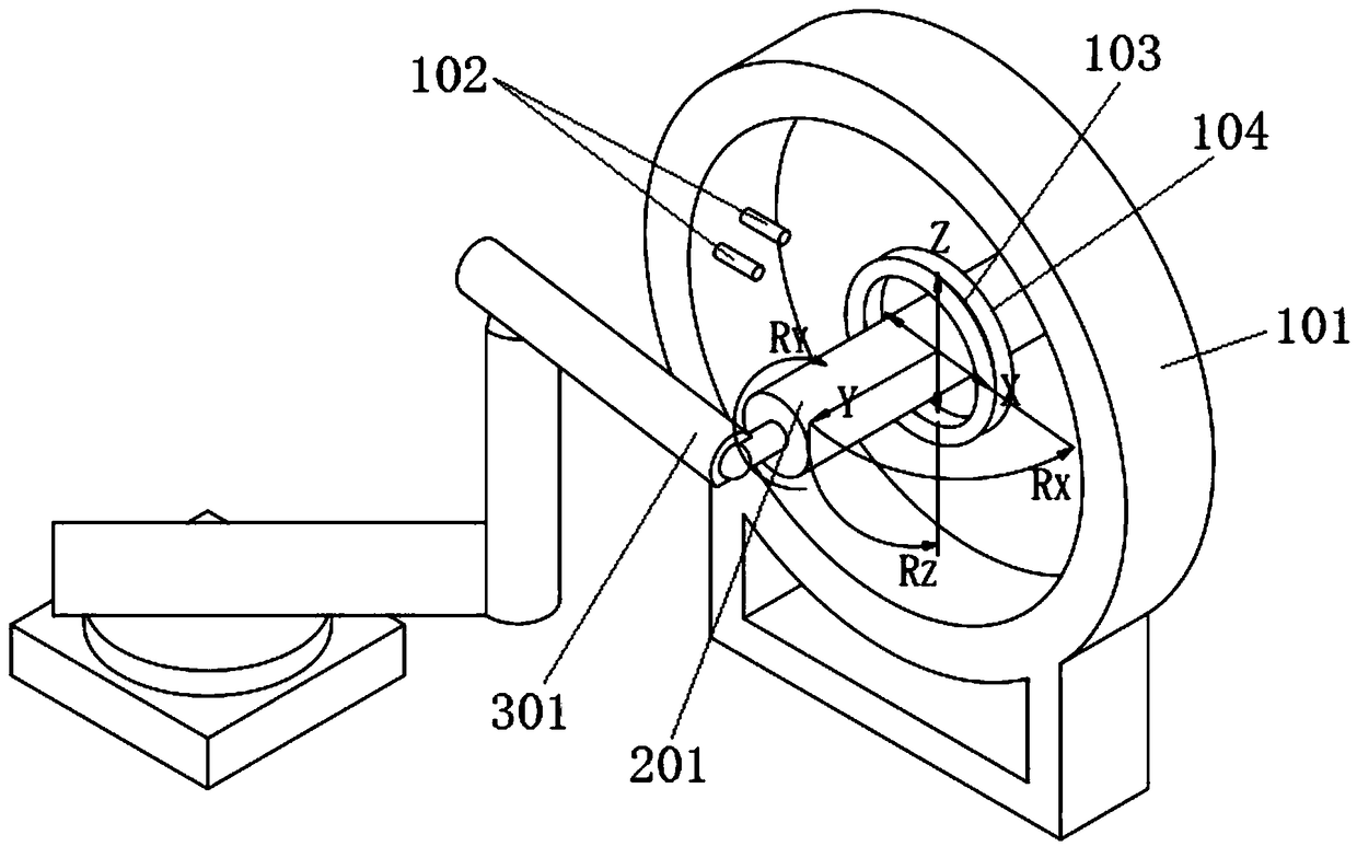
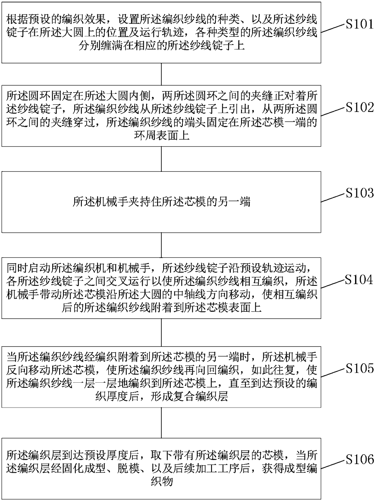
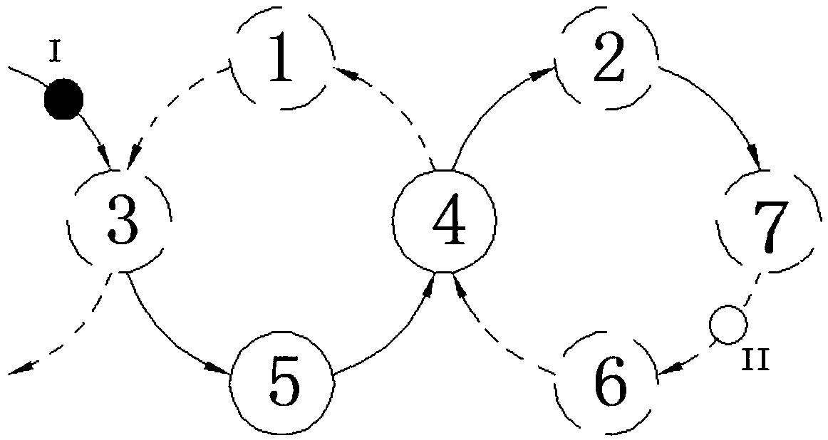

Image

  • Equipment and process for weaving composite material
  • Equipment and process for weaving composite material
  • Equipment and process for weaving composite material

Examples


Embodiment Construction

[0038] Exemplary embodiments of the present disclosure will be described in more detail below with reference to the accompanying drawings. Although exemplary embodiments of the present disclosure are shown in the drawings, it should be understood that the present disclosure may be embodied in various forms and should not be limited by the embodiments set forth herein. Rather, these embodiments are provided for more thorough understanding of the present disclosure and to fully convey the scope of the present disclosure to those skilled in the art. It should be noted that, in the case of no conflict, the embodiments of the present invention and the features in the embodiments can be combined with each other. The present invention will be described in detail below with reference to the accompanying drawings and examples.

[0039] refer to figure 1 As shown, the embodiment of the present invention provides a device for braiding composite materials, including: a braiding machine ...


PUM


Abstract

The invention provides equipment and a process for weaving a composite materials; the equipment comprises a knitting machine and a mechanical arm, the knitting machine comprises a large circle, yarn spindles, two circular rings and a core mould; the yarn spindles are arranged on the inner side wall of the large circle, and are uniformly arranged along the circumferential direction of the inner side wall of the large circle; the two circular rings are arranged side by side, the two circular rings coincide with the central axis of the large circle, and a preset distance is reserved between the two circular rings, so that woven yarns can pass through the preset distance; the core mould is arranged in the circular rings in a penetrating mode, one end of the core mould is connected with the mechanical arm, and the mechanical arm is used for driving the core mould to do reciprocating motion along the central axis direction of the large circle; the type of the yarn spindles is at least two, the yarn spindles of all types rotate synchronously with the large circle, and the large circle revolves according to a preset trajectory. An insulation operating rod produced by the weaving process and the equipment is higher in fiber density compared with other insulating rod formed by other processes, internal air bubbles are fewer, the insulation operating rod has the advantages of being lighter in weight, better in mechanical and insulating performance and capable of being applied to overhauling work of extra-high voltage electric power engineering.

Description

technical field [0001] The invention relates to the technical field of braiding and pultrusion forming of insulating operating rods for high-voltage electric power, in particular, to a device and process for braiding composite materials. Background technique [0002] At present, with the development of electric power engineering, the UHV power grid (AC 1000kV, DC ±800kV, ±1100kV) has become the backbone grid of the State Grid. Insulated operating rods are often required for maintenance work items. Due to the high voltage level and large insulation interval of the UHV system, the size and weight of the insulating operating rod doubled. In order to reduce the workload of the operators, it is necessary to develop a light-duty UHV maintenance on the basis of satisfying the electrical and mechanical strength of the operating rod. Use an insulated operating rod. [0003] At present, insulated operating rods are used for UHV maintenance in China, and the molding process of insula...

Claims


Application Information

Patent Timeline
Patent Type & Authority Applications(China)
IPC IPC(8): D04C3/04D04C3/48
CPCD04C3/04D04C3/48
Inventor 刘庭余光凯朱建军刘宝升陈利飞刘凯肖宾彭勇苏梓铭雷兴列唐盼郑秋玮沈茂东宋晓东付新阳董飞赵培
Owner STATE GRID CORP OF CHINA
Learn More