Unlock instant, AI-driven research and patent intelligence for your innovation.

Real-time imaging method for borehole wall based on cylindrical ultrasonic phased array

An ultrasonic phased array and real-time imaging technology, applied in earthwork drilling, wellbore/well components, measurement, etc., can solve problems such as troublesome data transmission, low useful signal amplitude, slow logging speed, etc., to improve image resolution Rate and detection accuracy, improved resolution and detection accuracy, and the effect of enhanced reflection echo amplitude

Inactive Publication Date: 2019-01-29
INST OF ACOUSTICS CHINESE ACAD OF SCI
View PDF13 Cites 6 Cited by
  • Summary
  • Abstract
  • Description
  • Claims
  • Application Information

AI Technical Summary

Problems solved by technology

Due to the single-shot and single-receive working method, if encountering complex or relatively harsh borehole conditions, the detected useful signal has a low amplitude and is difficult to identify, and some abnormal borehole wall structures and subtle changes are often difficult to identify
[0005] (2) The detection resolution is low
The sound beam radiated by conventional transducer probes is relatively wide. Although the concave focusing transducer can focus the sound beam, this focusing ability is very limited. Not only is the focus position fixed, it is difficult to adjust and adjust according to the actual situation. change, and the focused sound beam is not slender enough, making the image resolution of the detection data low
[0006] (3) Instability of mechanical rotation scanning
Mechanical rotation can also cause a lot of trouble for data transmission
[0007] (4) Logging speed is slow
However, these imaging methods directly use electromagnetic wave optical imaging, which cannot provide detailed direct imaging results due to the relative wavelength of sound waves to electromagnetic waves

Method used


Image

  • Real-time imaging method for borehole wall based on cylindrical ultrasonic phased array
  • Real-time imaging method for borehole wall based on cylindrical ultrasonic phased array
  • Real-time imaging method for borehole wall based on cylindrical ultrasonic phased array

Examples


Embodiment Construction

[0063] The present invention will be described in detail below in conjunction with the accompanying drawings and specific embodiments.

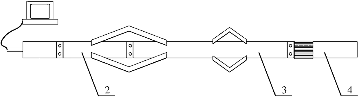
[0064] The overall structure of a wellbore imaging system based on cylindrical ultrasonic phased array provided by the present invention is as follows: figure 1 As shown, it includes: ground control and imaging system (ground controller 1), power supply sub-section 2, circuit sub-section 3, acoustic system sub-section 4 and external mechanical components. The sound system short section 4 includes a cylindrical ultrasonic phased array probe, and the cylindrical ultrasonic phased array probe is arranged in a cylindrical shape by a plurality of transducer array elements 6; the circuit short section 3 is based on the ground The control signal sent by the controller 1 controls each transducer element 6 in the cylindrical ultrasonic phased array probe to realize the focused transmission of ultrasonic signals and the focused reception of echo signal...


PUM


Abstract

Provided is a real-time imaging method for a borehole wall based on a cylindrical ultrasonic phased array. The method comprises: step 1) a ground controller (1) controlling an ultrasonic phased arrayprobe (11) and an instrument in a well to move uniformly along a well axis direction; step 2) the ultrasonic phased array probe (11) scanning the borehole wall in the circumferential direction for onecircle, that is, continuously transmitting ultrasonic waves to the borehole wall and receiving reflected echo signals from the borehole wall; and step 3) extracting time when receiving the echo signals, thereby calculating the distance from each point on the borehole wall to the center of a wellbore; step 4) extracting a peak value of the echo signals and converting the peak value to borehole wall color data; step 5) drawing the obtained distances between the wellbore wall and the center of the wellbore and the borehole wall color data in a narrow circular band; step 6) if detection is completed, going to step 7), otherwise, going to step 1) to obtain narrow circular bands at different times; step 7) connecting the narrow circular bands together to form a borehole wall image, to completea three-dimensional imaging process.

Description

technical field [0001] The invention relates to the field of ultrasonic imaging, in particular to a real-time imaging method of a borehole wall based on a cylindrical ultrasonic phased array. Background technique [0002] In the process of oil drilling and production, casing plays an important role in protecting the wellbore and strengthening the well wall to ensure the smooth progress of drilling. However, due to the harsh downhole environment, the number of casing damages is increasing year by year, and the detection and protection of casing walls has become an important task in oilfield development. Ultrasonic wellbore imaging detection technology is a commonly used oil well wellbore detection technology. By using the reflected echo information of the wellbore wall, it can identify various types of defects and the surrounding conditions of the wellbore, and clearly and intuitively display the condition of the wellbore wall and characteristic. [0003] In the 1990s, a ne...

Claims


Application Information

Patent Timeline
Patent Type & Authority Applications(China)
IPC IPC(8): E21B47/00E21B47/18E21B49/00
CPCE21B47/002E21B47/18E21B49/005
Inventor 高大亮师芳芳张碧星
Owner INST OF ACOUSTICS CHINESE ACAD OF SCI
Features
  • R&D
  • Intellectual Property
  • Life Sciences
  • Materials
  • Tech Scout
  • Unparalleled Data Quality
  • Higher Quality Content
  • 60% Fewer Hallucinations
Learn More