Natural ventilation counter flow cooling tower

A natural ventilation, counter-flow technology, applied in water shower coolers, direct contact heat exchangers, heat exchanger types, etc. Wind unevenness and other problems, to achieve the effect of improving the unevenness of wind speed distribution, improving efficiency, and improving uniformity

Pending Publication Date: 2019-01-29
MCC CAPITAL ENGINEERING & RESEARCH
View PDF0 Cites 4 Cited by
  • Summary
  • Abstract
  • Description
  • Claims
  • Application Information

AI Technical Summary

Problems solved by technology

[0012] The disadvantages of this kind of natural draft cooling tower are: firstly, due to the large heat load of the million-kilowatt power plant, the required circulating cooling water is relatively large, so the required cooling tower is large in scale and belongs to the super large cooling tower.
The head of the water pump required by the super-large cooling tower is relatively large. Due to the large amount of circulating cooling water, the power consumption of the circulating water pump accounts for about 2% of the power generation of the unit, and the operating cost is very high.

Method used


Image

  • Natural ventilation counter flow cooling tower
  • Natural ventilation counter flow cooling tower
  • Natural ventilation counter flow cooling tower

Examples


Example Embodiment

[0044] It should be noted that the embodiments in this application and the features in the embodiments can be combined with each other if there is no conflict. Hereinafter, the present invention will be described in detail with reference to the drawings and in conjunction with the embodiments.

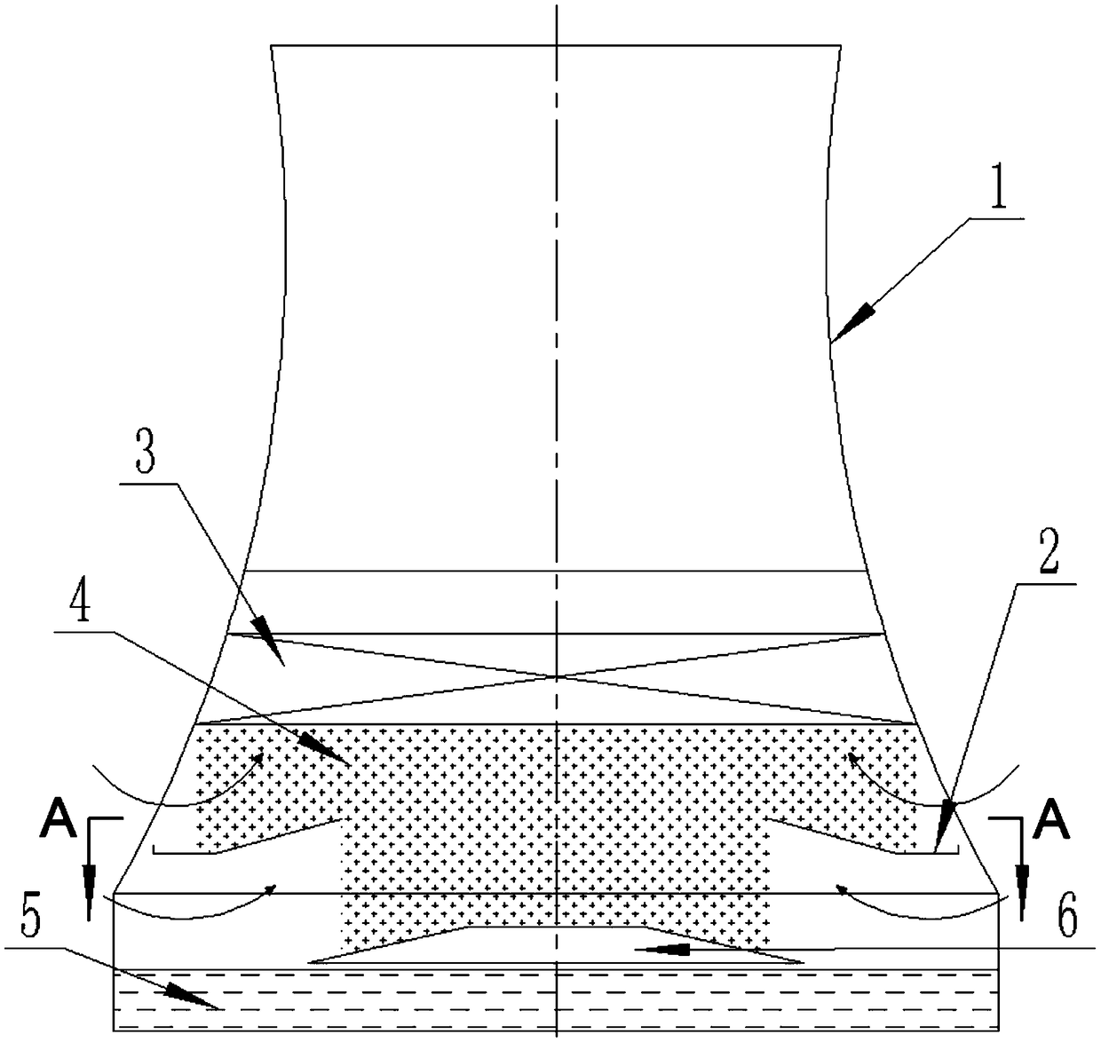
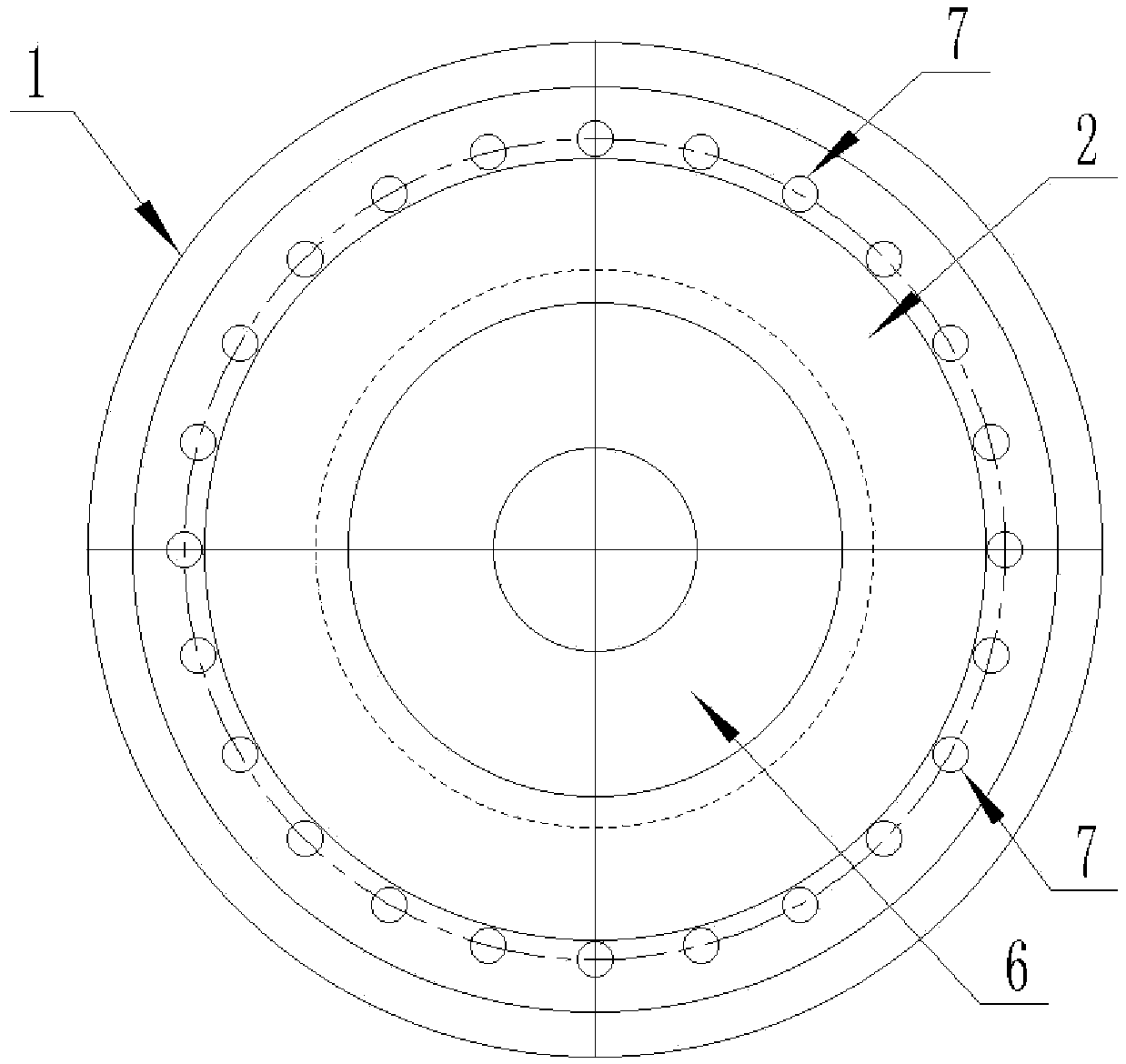
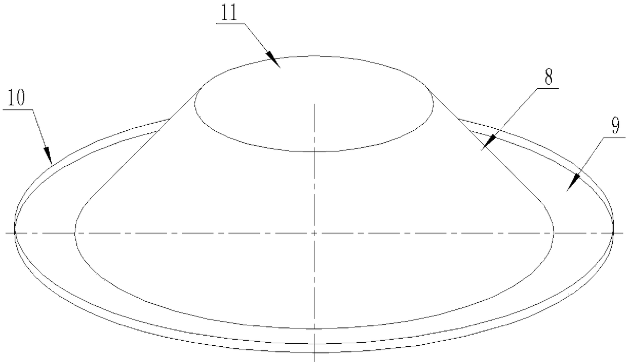
[0045] A natural ventilation counter-flow cooling tower, comprising a tower shell 1, an air inlet baffle 2 is arranged in the tower shell 1, and the air inlet baffle 2 includes a cylindrical section 8 and a circle connected in order from the inside to the outside. The ring section 9 and the water retaining section 10, the cylindrical section 8 is an upright truncated cone-shaped cylindrical structure, the ring section 9 is a horizontal concentric circular ring structure, and the water retaining section 10 is an upright cylindrical structure. The top end of the section 8 faces upwards, the top end of the cylindrical section 8 is provided with a ventilation hole 11, the bottom end of the cy...


PUM

PropertyMeasurementUnit
Bottom corneraaaaaaaaaa

Abstract

The invention discloses a natural ventilation counter flow cooling tower. The cooling tower comprises a tower shell (1). An air inlet flow guide plate (2) and a flow guide circular truncated cone (6)are arranged in the tower shell (1). A cylinder segment (8), a circular ring segment (9) and a water retaining segment (10) which are sequentially connected from inside to outside are contained in theair inlet flow guide plate (2). According to the natural ventilation counter flow cooling tower, cold air of the cooling tower air inlet area is layered by means of the air inlet flow guide plate, meanwhile, the flow rates of cold air entering the side portion and the center area of the cooling tower are regulated by regulating the height of the air inlet flow guide plate, control over differentflow rates of different areas is achieved, impeding of a rainfall area on the airflow of the center area is eliminated, and the flow speed of the air of the center area is increased; and vertical steering of airflow in the center of the bottom of the cooling tower is achieved, the flowing speed of the airflow in the center is increased, the cooling strength of the center area is improved, the uniformity and stability of the temperature of cooling water of the cross section of the cooling tower are achieved, and the cooling efficiency of the cooling tower is improved.

Description

technical field [0001] The invention relates to a natural draft counterflow cooling tower. Background technique [0002] The waste heat generated in industrial production or refrigeration process should be conducted away with cooling water. The cooling water carrying waste heat exchanges heat with the air in the cooling tower, and through evaporation, the waste heat is transferred to the air and diffused into the atmosphere. [0003] In the process of waste heat exchange, the high-temperature cooling water is delivered to the water spreading system on the upper part of the cooling tower through the water pump in the main engine room at a certain pressure, and the hot water is evenly spread on the surface of the filler through the small holes on the water spreader to form water droplets and water films. The dry air enters the cooling tower from the air inlet at the bottom of the cooling tower supported by the herringbone column, and the high-temperature water molecules in th...

Claims


Application Information

Patent Timeline
IPC IPC(8): F28C1/02F28F25/12
CPCF28C1/02F28F25/12
Inventor 耿明山金锐韩庆礼
Owner MCC CAPITAL ENGINEERING & RESEARCH
Why Eureka
Try Eureka