Detection system for chips adhering to electric spindle of numerical-control machine tool

A CNC machine tool and detection system technology, applied in the direction of measuring/indicating equipment, metal processing machinery parts, metal processing equipment, etc., can solve the problems of increasing product production costs, waste of resources, long measurement time, etc., to improve work stability, The effect of high measurement sensitivity and reduced production costs

Active Publication Date: 2019-02-01
YANTAI UNIV
View PDF7 Cites 8 Cited by
  • Summary
  • Abstract
  • Description
  • Claims
  • Application Information

AI Technical Summary

Problems solved by technology

[0006] Although contact measurement technology has certain applications in workpiece positioning, coordinate setting, measuring the geometric size and three-dimensional shape of parts, tool parameters, tool wear detection, etc., it has uneven force, long measurement time, and space for measurement points. Insufficient resolution to measure birth defects such as soft objects
At the same time, due to the influence of centrifugal force, the application of contact sensors in high-speed rotation of machine tool spindles, cutting processing, etc. is also greatly restricted.
[0007] Although the detection method of the built-in sensor in the tool handle makes up for the shortcomings of the traditional contact measurement method, it may require multiple tools of different specifications to process a workpiece during the machining process. If all the tool handles have The same sensor detection device will undoubtedly increase the production cost of the product, reduce the market competitiveness of the product, and cause waste of resources, which violates the principle of green environmental protection and sustainable development

Method used


Image

  • Detection system for chips adhering to electric spindle of numerical-control machine tool
  • Detection system for chips adhering to electric spindle of numerical-control machine tool
  • Detection system for chips adhering to electric spindle of numerical-control machine tool

Examples


Embodiment Construction

[0035] The principles and features of the present invention are described below in conjunction with the accompanying drawings, and the examples given are only used to explain the present invention, and are not intended to limit the scope of the present invention.

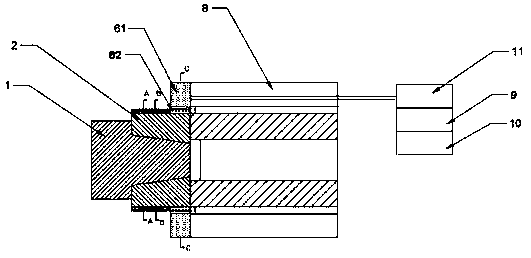
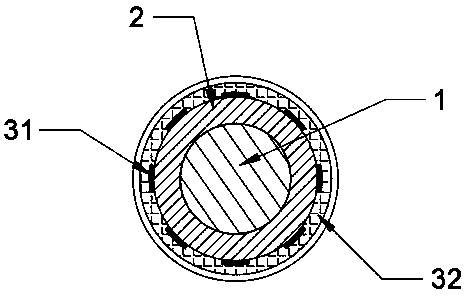
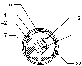
[0036] Please refer to Figure 1~Figure 6 As shown, the chip sticking detection system for the electric spindle for CNC machine tools includes: a tapered fixture body 2, a sensor module 3, a signal processing module 4, a power supply module 5, a wireless power supply module 6, a signal transmitting module 7, an electric spindle housing 8, An electric spindle, a data processing module 9, an alarm module 10, and an external power supply 11 set in the electric spindle housing 8;

[0037] The sensor module 3, the signal processing module 4, the power module 5, and the signal transmitting module 7 are arranged on the outer circular surface of the tapered fixture body 2; the power module 5 is connected to the sensor modul...


PUM


Abstract

The invention discloses a detection system for chips adhering to an electric spindle of a numerical-control machine tool. The detection system comprises a conical clamp body, a power supply module, asensor module, a signal processing module and a signal transmitting module. The power supply module, the sensor module, the signal processing module and the signal transmission module are arranged onthe outer surface of the conical clamp body. The sensor module is formed by at least four resistance strain gauges which are connected into a full-bridge circuit. The resistance strain gauges are evenly distributed on the outer circular surface of the conical clamp body. The signal processing module is used for converting a weak analog signal detected by the sensor module into a digital signal. The signal transmission module is used for wirelessly transmitting detected data. A detection device is integrated on a conical clamp of the spindle, and the full-bridge detection circuit is used, so that the detection sensitivity is high; and an alarm critical value can be preset, so that frequent value calibration is not needed, and the detection stability and reliability are improved.

Description

technical field [0001] The invention relates to the field of numerical control machine tools, in particular to a chip sticking detection system for electric spindles used in numerical control machine tools. Background technique [0002] CNC machine tools are the main machine tools of the equipment manufacturing industry, and machining centers are the most important members of CNC machine tools. Due to the concentration of processes and automatic tool change in the machining center, the time for clamping, measuring and machine tool adjustment of the workpiece is reduced, so that the cutting time of the machine tool reaches about 80% of the machine tool start-up time (only 15-20% for ordinary machine tools); at the same time It also reduces the workpiece turnover, handling and storage time between processes, shortens the production cycle, and has obvious economic effects. Machining centers are suitable for small and medium-sized batch production with complex parts shapes, hig...

Claims


Application Information

Patent Timeline
Patent Type & Authority Applications(China)
IPC IPC(8): B23Q17/00
CPCB23Q17/00
Inventor 柴永生李林刘宇航王琦刘希宽董建权张振峰李岩王昌辉
Owner YANTAI UNIV
Why Eureka
Try Eureka