Temperature difference control method for quick cooling or quick starting of turbine

A rapid start-up and temperature difference control technology, which is applied in the direction of engine start-up, machine/engine, mechanical equipment, etc., can solve the problems of uncommon use of devices, affecting the life of steam turbines, long residence time, etc., to avoid excessive metal stress and ensure use The effect of longevity

Inactive Publication Date: 2019-02-01
ZHEJIANG OCEAN UNIV
View PDF5 Cites 7 Cited by
  • Summary
  • Abstract
  • Description
  • Claims
  • Application Information

AI Technical Summary

Problems solved by technology

[0003] In addition, after the steam turbine generator set is overhauled, the steam turbine is in a cold state. During the start-up process of the unit, the steam turbine needs to be warmed up due to mechanical reasons. At this time, the steam parameters are low and the residence time is long. It usually takes 5 to 6 hours from start-up to grid connection. , it will take 3 to 4 hours to reach the flue gas temperature when the denitrification catalyst is put into operation after being connected to the grid. During the start-up process of the unit, the boiler cannot reach the ideal working state for 8 to 10 hours, the denitrification device cannot be normally put into operation, and NOX nitrogen oxide pollutants The emissions s

Method used


Image

  • Temperature difference control method for quick cooling or quick starting of turbine
  • Temperature difference control method for quick cooling or quick starting of turbine
  • Temperature difference control method for quick cooling or quick starting of turbine

Examples


Embodiment

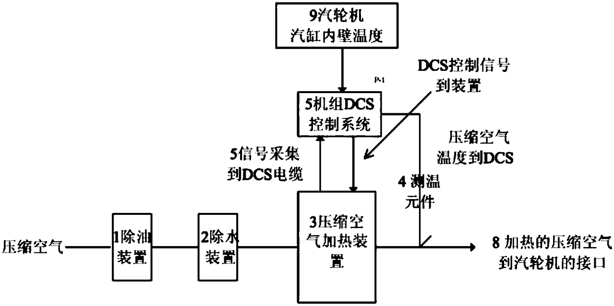
[0028] figure 1 It is a schematic diagram of a quick start device. As shown in the figure, the compressed air enters the inlet 8 of the steam turbine through the oil removal device 1, the water removal device 2, and the compressed air motor heater 3. There is also a temperature measuring element 4 in the figure, and the unit DCS control system 5, steam turbine cylinder inner wall temperature 9.

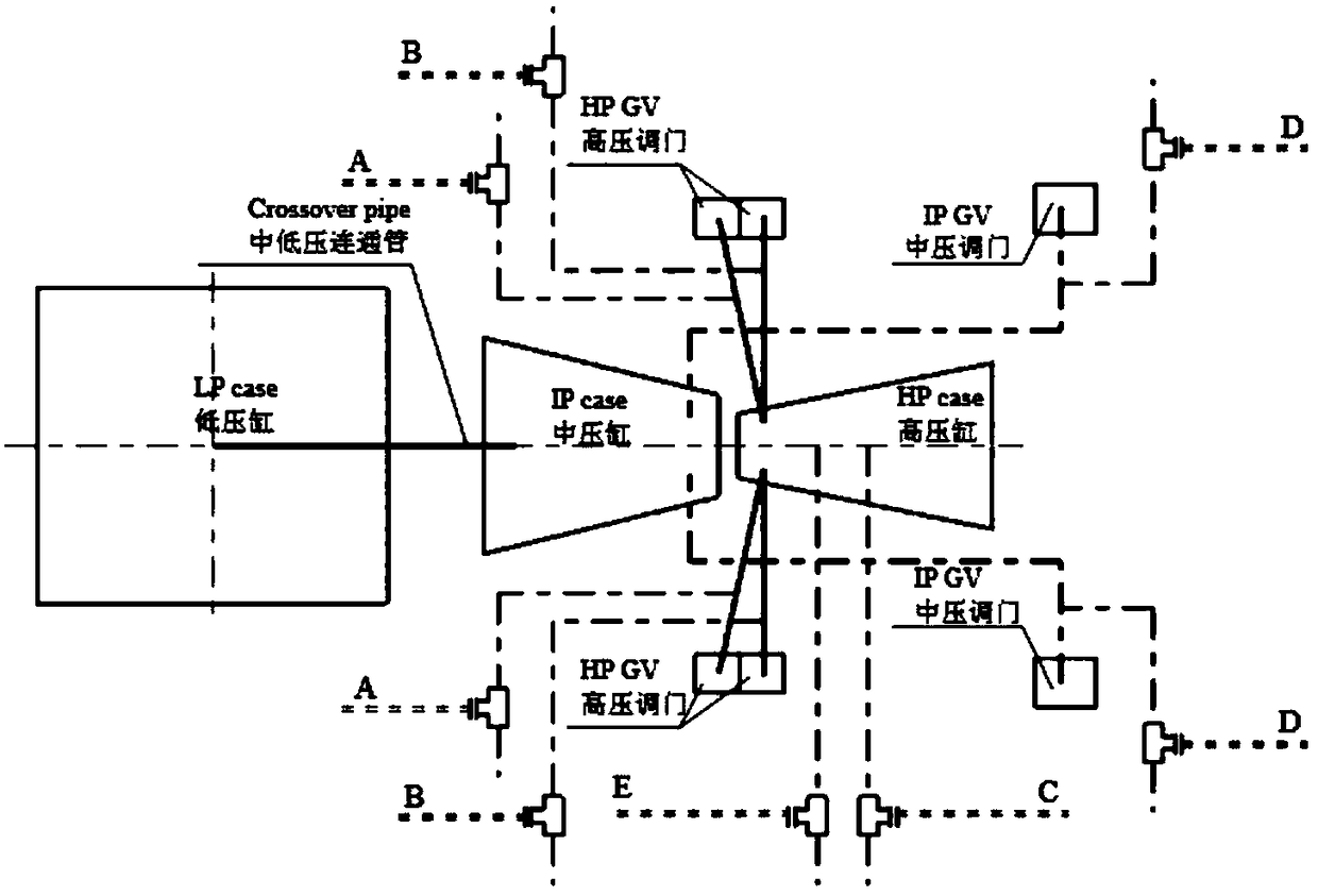
[0029] figure 2 The interface system diagram of the compressed air heated for a certain unit and the steam turbine; as shown in the figure:

[0030] Air inlet: the air inlet port of the high-pressure flow part,

[0031] A: Before the vent valve of the high-pressure steam inlet pipe (steam guide pipe)

[0032] B: Before the steam trap of the high-pressure steam inlet pipe (steam guide pipe)

[0033] C: Before the high-pressure inner cylinder drain valve

[0034] The air inlet port of the flow part of the medium pressure cylinder,

[0035] D: Before the steam trap of the medium p...


PUM


Abstract

Disclosed is a temperature difference control method for quick cooling or quick starting of a turbine. According to the temperature difference control method, a turbine quick cooling or quick startingdevice is used for compressing air through electric heating, heated air is conveyed into a high-intermediate pressure cylinder of the turbine, quick cooling is carried out according to certain rate,or the metal temperature of the high-intermediate pressure cylinder is improved. The temperature difference control method comprises the steps that a) quick cooling, wherein the compressed air is firstly heated to 280 DEG C, a valve is opened to convey the compressed air into the high-intermediate pressure cylinder, and the cooling rate of the compressed air is automatically controlled to accelerate turbine cooling; and b) quick starting, wherein at the normal-temperature stage before unit starting, air of certain temperature is conveyed into the turbine, a certain temperature difference between the air and the inner wall of the steam cylinder is kept, the temperature of the steam cylinder is improved according to a certain rate within the specified range to achieve the arm of heating theturbine. The temperature difference control method has the beneficial effects that the temperature of the compressed air and the temperature rise or cooling rate of turbine metal can be controlled, the stress of the turbine metal is prevented from exceeding the standard, and the service life of the turbine is guaranteed.

Description

technical field [0001] The invention relates to a temperature difference control method for quick cooling or quick start of a steam turbine, belonging to the technical field of steam turbine generators. Background technique [0002] There is a certain time limit for the planned maintenance time of steam turbines. Due to the good thermal insulation performance of steam turbines and the long cooling time of steam turbines, the waiting time for steam turbine maintenance is greatly increased. The larger the capacity of a single unit, the greater the contradiction. In order to speed up the cooling speed of the steam turbine cylinder, a steam turbine rapid cooling device is currently used to shorten the cooling time of the steam turbine. [0003] In addition, after the steam turbine generator set is overhauled, the steam turbine is in a cold state. During the start-up process of the unit, the steam turbine needs to be warmed up due to mechanical reasons. At this time, the steam pa...

Claims


Application Information

Patent Timeline
IPC IPC(8): F01D19/02F01D25/10F01D25/12
CPCF01D19/02F01D25/10F01D25/12
Inventor 沈晓群苏玉香杨震力叶继英
Owner ZHEJIANG OCEAN UNIV
Why Eureka
Try Eureka