Method for improving interface of all-solid-state thin film secondary lithium ion battery positive electrode and electrolytic layer thin film
A lithium-ion battery, electrolytic layer technology, applied in secondary batteries, battery electrodes, non-aqueous electrolyte batteries, etc., can solve the problem of poor ionic conductivity, solid-state secondary lithium-ion battery output performance such as poor current and capacity, poor contact interface and other problems, to achieve the effect of improving uniformity, improving output current density and fast charge and discharge characteristics, and reducing deposition thickness
- Summary
- Abstract
- Description
- Claims
- Application Information
AI Technical Summary
Problems solved by technology
Method used
Image
Examples
Embodiment 1
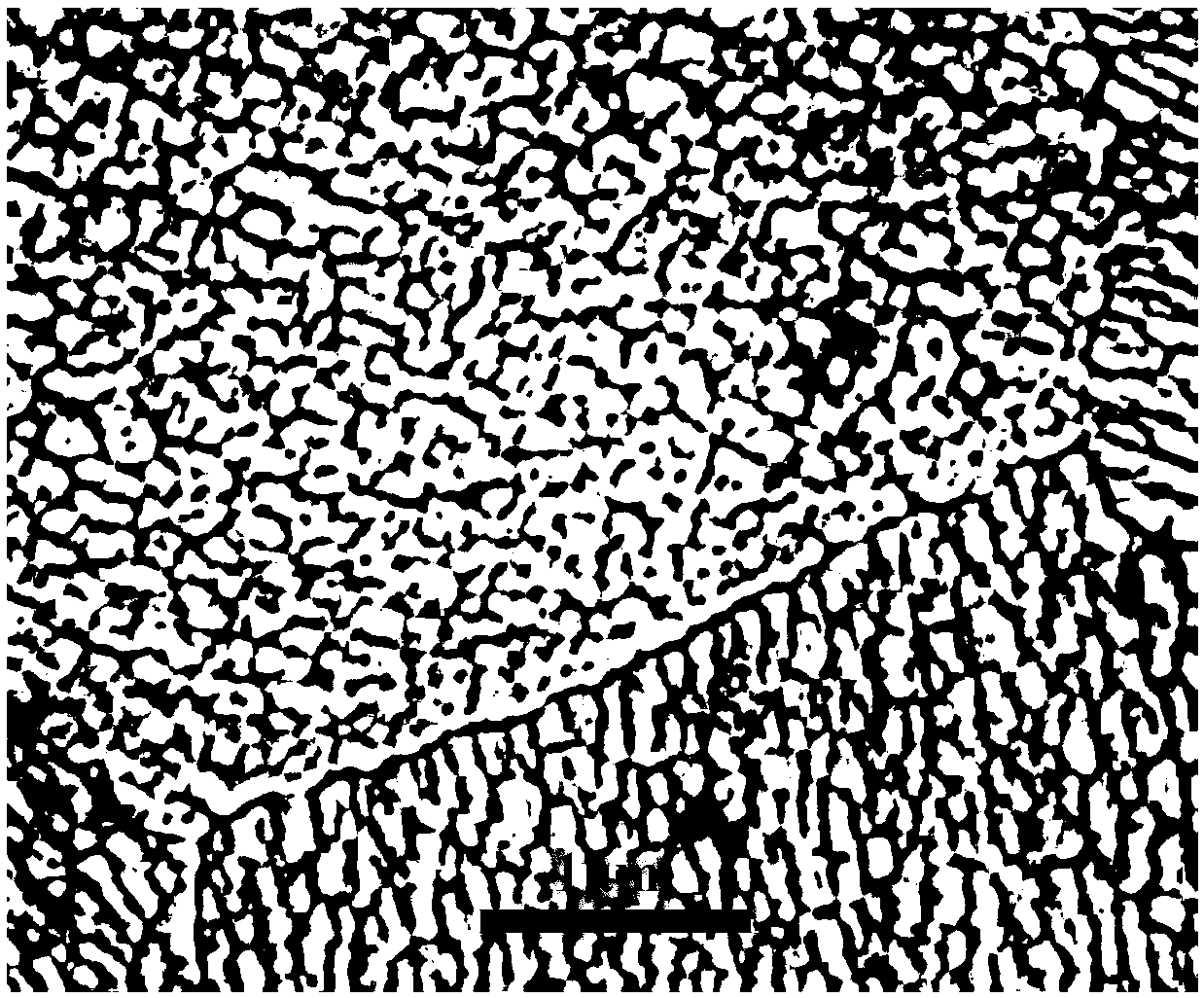
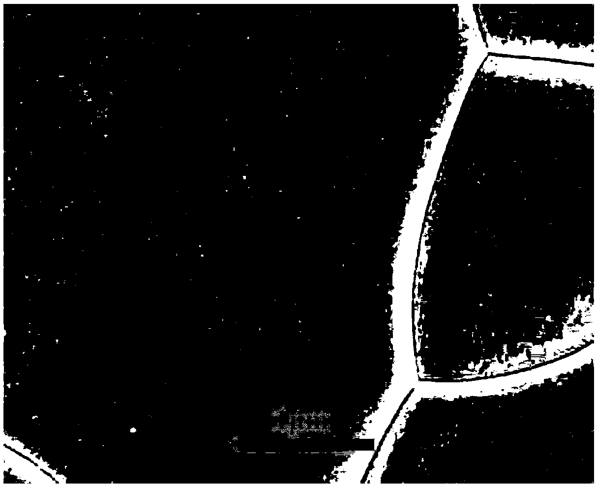
[0016] Using LiNi 1 / 3 co 1 / 3 Al 1 / 3 o 2 As the cathode material, LiCoO 2 After preparing the slurry, the LiCoO 2 The slurry was cast into a 10-micron substrate, and then heat-treated at 400° C. to form a dense positive electrode material substrate. The prepared cathode material substrate is put into the chamber of the plasma processing equipment, the power of the used plasma is 90KW, adopts O 2 Plasma sources combined with F-containing compounds, for LiCoO 2 One side of the substrate was subjected to scanning bombardment etching, and the etching time was 0.5 hours. Then, the magnetron plasma sputtering method is used in situ to deposit a thin film with the same composition as the positive electrode material on the etched positive electrode material substrate, and the sputtering power is 110KW. Sputter for 1 hour. After the sputtering is completed, plasma is used to etch the surface for 0.5 hour to obtain a flat and smooth positive electrode material surface.
Embodiment 2
[0018] Using LiNi 1 / 3 co 1 / 3 Al 1 / 3 o 2 As the cathode material, LiCoO 2 After preparing the slurry, the LiCoO 2 The slurry is cast into a 200-micron substrate, and then heat-treated at 850° C. to form a dense positive electrode material substrate. Put the prepared cathode material substrate into the chamber of plasma processing equipment, the power of the plasma used is 150KW, and the plasma source combining Ar and F-containing compound is used to treat LiCoO 2 One side of the substrate was etched by scanning bombardment for 3 hours. Then, the magnetron plasma sputtering method is used in situ to deposit a thin film with the same composition as the positive electrode material on the etched positive electrode material substrate, and the sputtering power is 150KW. Sputter for 3 hours. After the sputtering is completed, plasma is used to etch the surface for 1 hour to obtain a flat and smooth positive electrode material surface.
Embodiment 3
[0020] Using LiNi 0.6 co 0.2 mn 0.2 o 2 (LNCM) positive electrode material, adopt the method used in embodiment 1 to prepare dense positive electrode material substrate, then fix the positive electrode material substrate on the chemical mechanical polishing machine and carry out CMP polishing. The polishing agent uses diamond, CMP polishing for 1 hour, and then adopts the magnetron sputtering process in Example 1 to deposit a layer of LNCM on the polished surface, and then uses plasma to etch the surface for 0.5 hours to obtain a smooth positive electrode material surface.
PUM
 Abstract
Description
Claims
Application Information
 - R&D
- Intellectual Property
- Life Sciences
- Materials
- Tech Scout
- Unparalleled Data Quality
- Higher Quality Content
- 60% Fewer Hallucinations
Browse by: Latest US Patents, China's latest patents, Technical Efficacy Thesaurus, Application Domain, Technology Topic, Popular Technical Reports.
© 2025 PatSnap. All rights reserved.Legal|Privacy policy|Modern Slavery Act Transparency Statement|Sitemap|About US| Contact US: help@patsnap.com


