
An oil drill adopts a bolter with protective function

A protection function, the technology of bolt drilling rig, applied in drilling tools, installation of bolts, earthwork drilling and other directions, can solve problems such as drilling rig shaking, drill pipe damage, accidental injury, etc., to ensure structural flexibility and expand drilling. The area and structure are complete and perfect

Inactive Publication Date: 2020-06-23
魏武康
View PDF6 Cites 0 Cited by
  • Summary
  • Abstract
  • Description
  • Claims
  • Application Information

AI Technical Summary

Problems solved by technology

[0004] The purpose of the present invention is to provide a kind of oil drill adopting the rock bolt machine with protection function, to solve the existing big defect in the vertical drilling depth hole of the existing rock bolt machine proposed in the above-mentioned background technology, the surface rock is hard, and the drill There is only one rod, and it is very easy to cause damage to the drill rod and cause serious deformation during strong drilling, which in turn affects the service life and efficiency of the rock bolter. Moreover, the ability of the bolter to position before drilling is poor. During the drilling process, the drill It is easy to produce very large vibration, and then the force on the drill pipe is not balanced and stable, which seriously affects the straightness of drilling. At the same time, it is also very easy to cause rock splashing and accidental injury.

Method used


Image

  • An oil drill adopts a bolter with protective function
  • An oil drill adopts a bolter with protective function
  • An oil drill adopts a bolter with protective function

Examples


Embodiment Construction

[0030] The following will clearly and completely describe the technical solutions in the embodiments of the present invention with reference to the accompanying drawings in the embodiments of the present invention. Obviously, the described embodiments are only some, not all, embodiments of the present invention. Based on the embodiments of the present invention, all other embodiments obtained by persons of ordinary skill in the art without making creative efforts belong to the protection scope of the present invention.

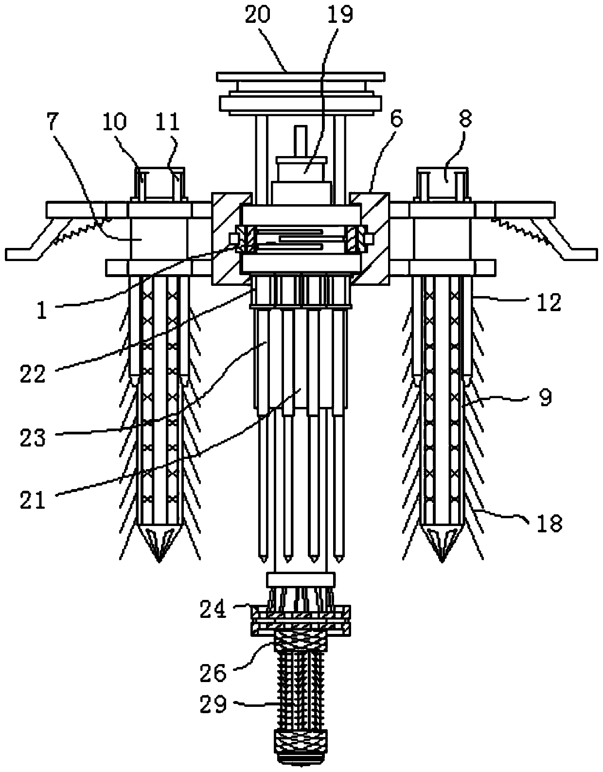
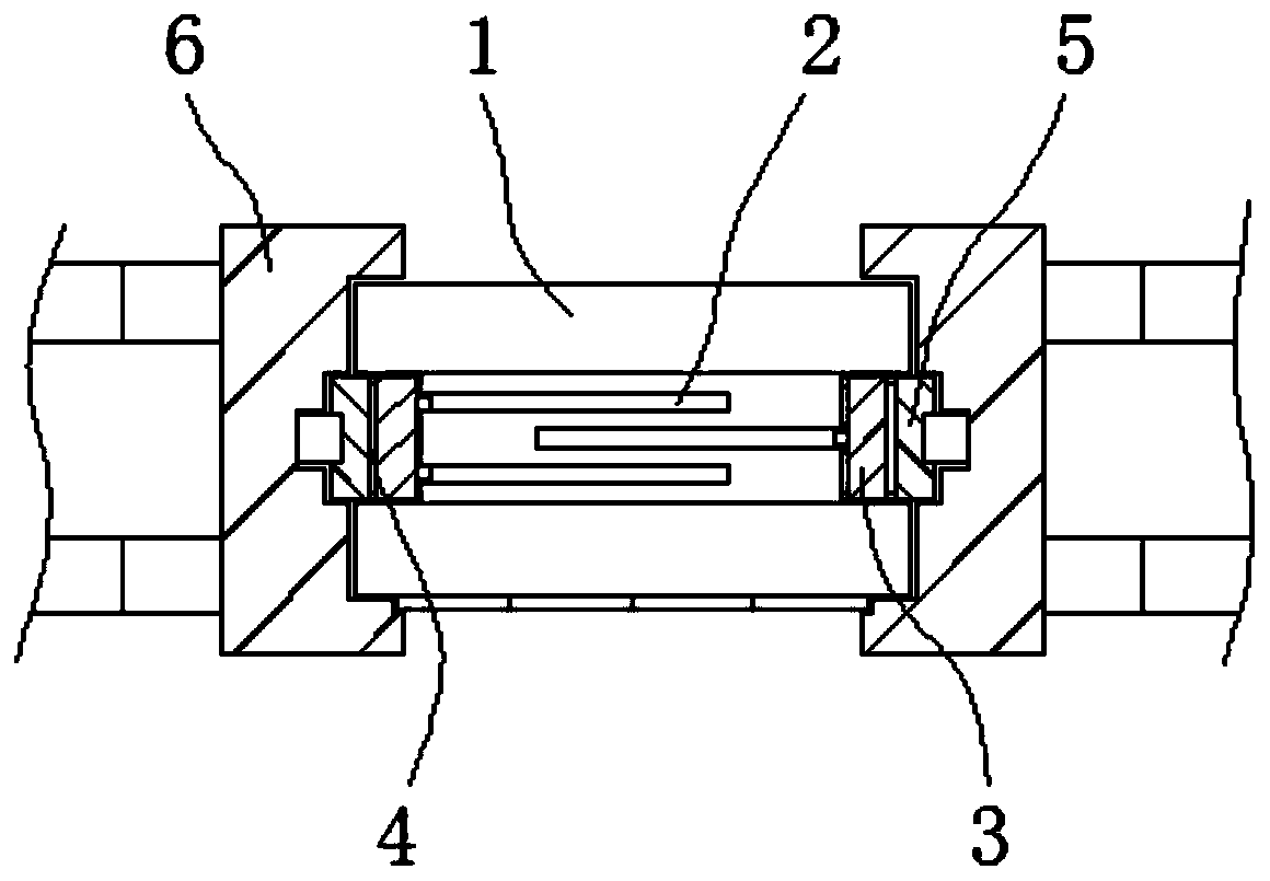
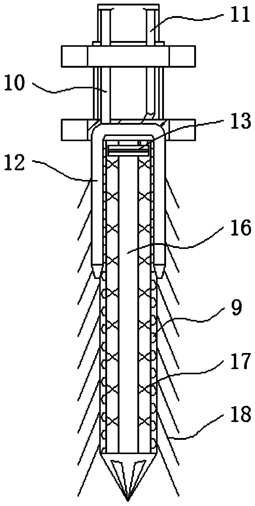
[0031] see Figure 1-8, the present invention provides a technical solution: a kind of oil drill adopts a rock bolter with protective function, including a top seat 1, an auxiliary drill pipe 7 and a main drill pipe 21, and a chute 2 is arranged on the surface of the top seat 1, In addition, an inner slide ring 3 is arranged on the outside of the middle of the top seat 1, and the dimensions between the inner slide ring 3 and the chute 2 match each other. The o...


PUM


Abstract

The invention discloses an anchor drilling machine provided with a protection function and used for oil drilling. The anchor drilling machine provided with the protection function and used for oil drilling comprises an installation top seat, auxiliary drilling rods and a main drilling rod. A sliding groove is formed in the surface of the installation top seat, an inner sliding ring is arranged onthe outer side of the middle of the installation top seat, a control motor seat is arranged at the upper end of the auxiliary drilling rod, the auxiliary drilling rods are separately positioned on theleft and right sides of a collar plate, a hydraulic cylinder is arranged above the outer side of the main drilling rod, and the main drilling rod is positioned below the collar plate. According to the anchor drilling machine provided with the protection function and used for oil drilling, the sizes of the collar plate and an outer sliding ring are matched with each other, the outer sliding ring is arranged on the outer side of the mounting top seat in a clamped mode and is attached to a cushion layer on the outer wall of the inner sliding ring, and the size of the inner sliding ring is matched with the size of the sliding groove on the installation top seat, namely, the inner sliding ring has rotating capability on the installation top seat, the outer sliding ring has rotating capabilityon the cushion layer, and the collar plate has rotating capability on the outer sliding ring, so that the collar plate has very high rotating flexibility in a layer-by-layer nesting mode.

Description

technical field [0001] The invention relates to the technical field of rock bolts, in particular to a rock bolt with protective functions for oil drilling. Background technique [0002] Anchor drilling rigs are also called anchor drilling rigs in some places. They are drilling tools used in coal mine roadway bolt support. It has very prominent advantages in terms of strength and improving the utilization rate of roadway sections. It will also be applied to rock bolters in oil drilling. Oil is the most precious wealth bestowed by nature on human beings. Oil is also called "industrial blood". Exploitation of oil should require reasonable planning. After all, oil resources are limited and oil production takes too long. Humans should exercise reasonable restraint in the development of oil projects. [0003] However, the existing rock bolts have relatively large defects in vertical drilling of deep holes. The surface rock is hard, and there is only one drill pipe. It is very eas...

Claims


Application Information

Patent Timeline
Patent Type & Authority Patents(China)
IPC IPC(8): E21D20/00E21B7/00E21B15/00E21B21/16E21B3/02E21B12/00
CPCE21B3/02E21B7/00E21B12/00E21B15/00E21B21/16E21D20/003
Inventor 梁水玲
Owner 魏武康
Learn More