Novel wideband four-way filtering power divider

A filter and broadband technology, applied in the field of microwave passive devices, can solve the problems of poor in-band isolation level, lack of wide stop-band performance, and large circuit size, etc., to achieve easy processing and integration, and good out-of-band suppression performance , the effect of low production cost

Active Publication Date: 2019-02-12
NANJING NORMAL UNIVERSITY
View PDF5 Cites 6 Cited by
  • Summary
  • Abstract
  • Description
  • Claims
  • Application Information

AI Technical Summary

Problems solved by technology

[0003] Literature 1 [F.J.Chen, L.S.Wu, L.F.Qiu, and J.F.Mao, "A four-way microstripfiltering power divider with frequency-dependent couplings," IEEE Trans. Microw. Theory Techn., vol.63, no.10, pp.3494– 3504,Oct.2015.] proposed a microstrip line-type four-power division filter, however, it does not have wide stopband performance, and the isolation level in the band is not good
[0004] Document 2 [H.Zhu, A.M.Abbosh and L.Guo, "Wideband four-way filtering powerdivider with sharp selectivity and wide stopband using looped coupled-linestructures," IEEE Microw.Wireless Compon. Lett., vol.26, no.6 ,pp.413-415,Jun.2016.] proposed a power division filter with wide stopband performance, however, the problems of large insertion loss and poor selectivity limit the wide application of the power division filter
[0005] Document 3 [C.Zhu, J.Xu and W.Wu, "Microstrip four-way reconfigurable single / dual / wide-band filtering power divider with tunable frequency, bandwidth, and PDR," IEEE Trans.Ind.Electron.vol. PP ,Apr.2018.] Based on four multimode resonators, a reconfigurable four-power split filter with wide stopband characteristics was designed, but the number of resonators determines its circuit size is too large, which is not conducive to practical applications

Method used


Image

  • Novel wideband four-way filtering power divider
  • Novel wideband four-way filtering power divider
  • Novel wideband four-way filtering power divider

Examples


Embodiment 1

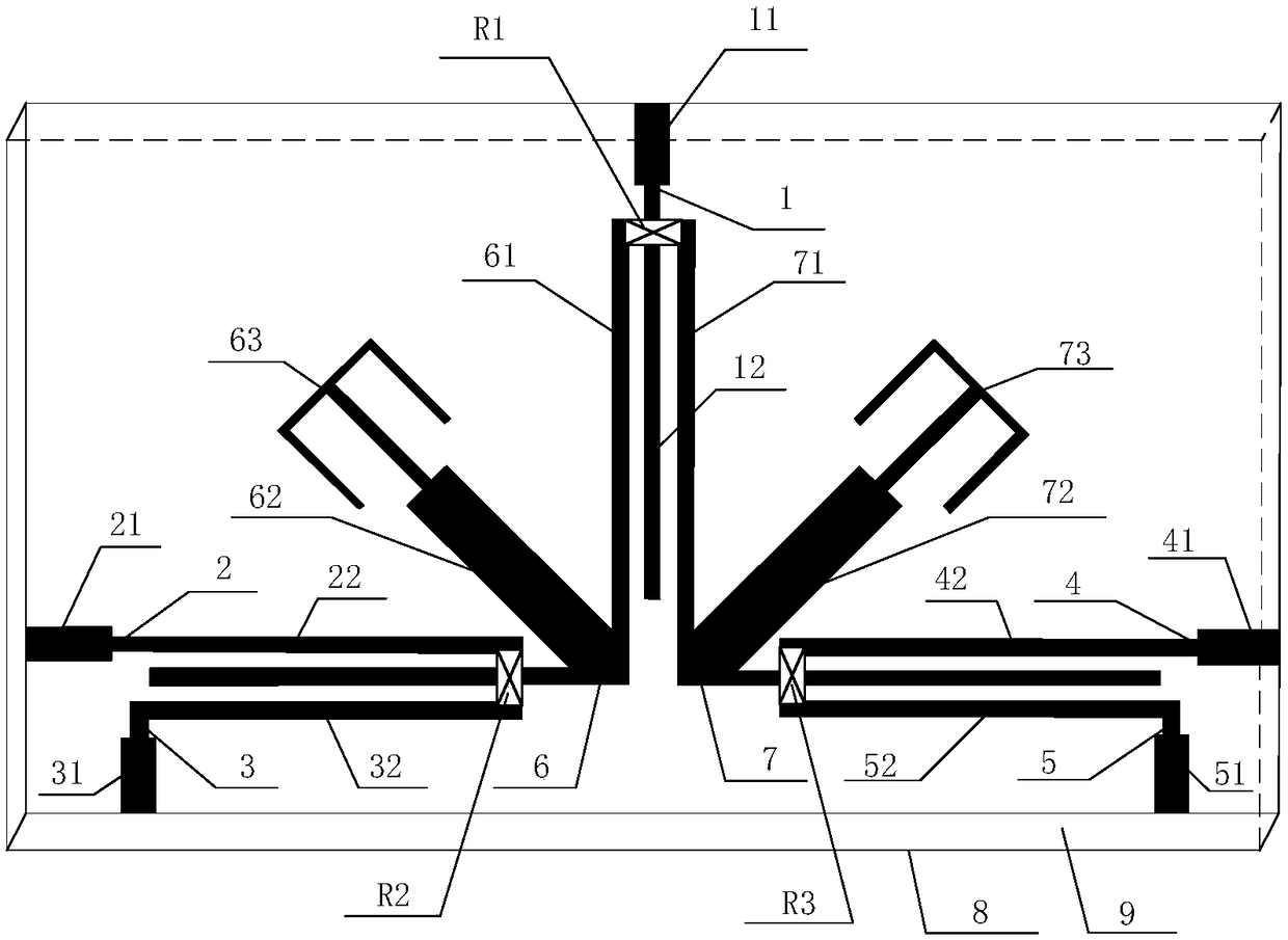
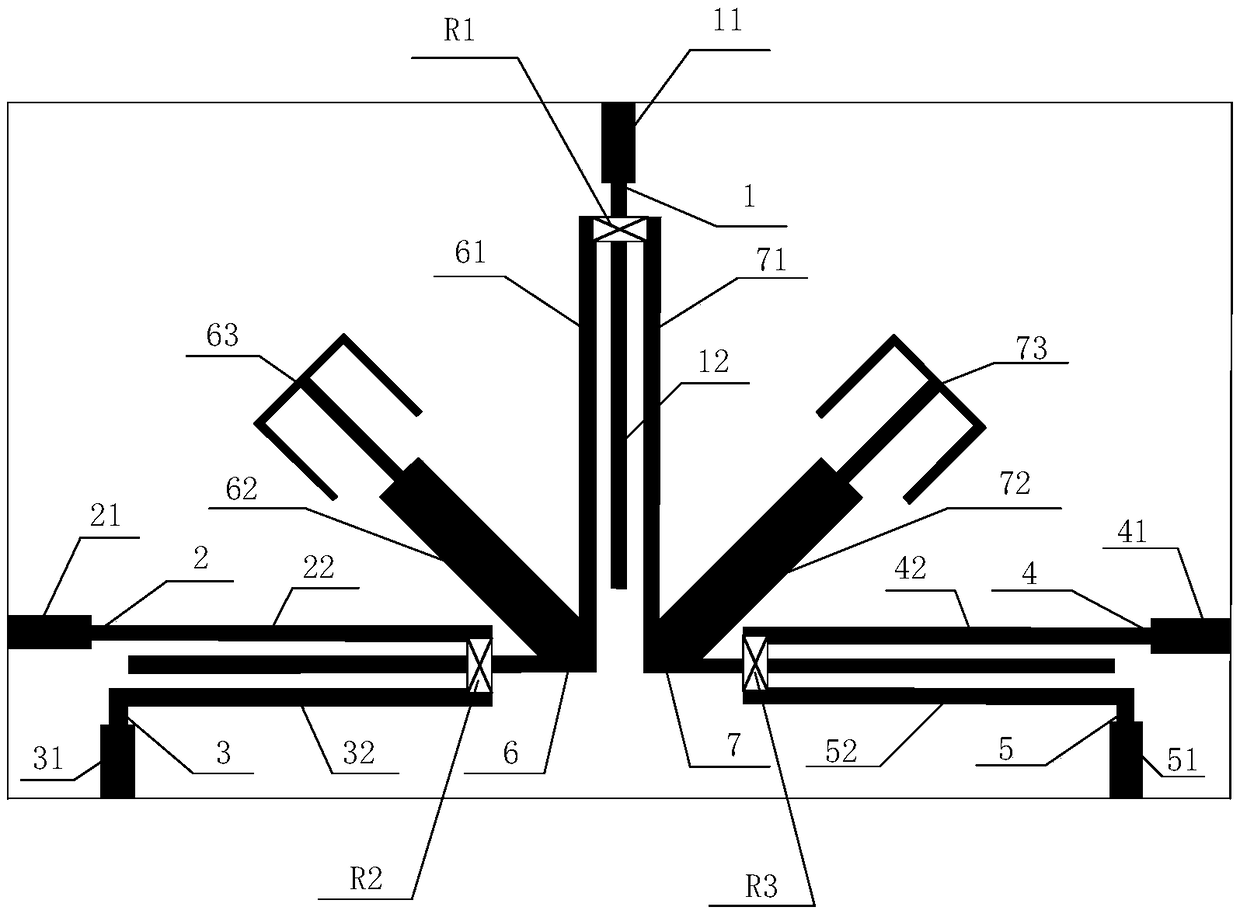
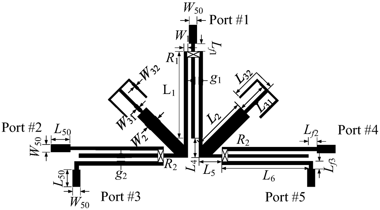
[0059] The structure of a new type of broadband four power division filter is as follows: figure 1 As shown, the top view is as figure 2 As shown, the relevant dimensions and specifications are as follows image 3 shown. The dielectric substrate 9 used has a relative permittivity of 3.55, a thickness of 0.508 mm, and a loss tangent of 0.0027. combine image 3 , the size parameters of the wideband four-power division filter are as follows: L 1 =24.6mm,L 2 =17.3mm,L 31 =9.7mm, L 32 =12.6mm,L 4 =3mm,L 5 =3mm,L 6 =21.6mm, L 50 =5mm,L f1 =2.2mm,L f2 =2.2mm,L f3 =2.2mm, W 50 =1.18mm,W 1 =0.48mm,W 2 =3mm,W 31 =0.3mm,W 32 =0.15mm,g 1 =0.16mm,g 2 =0.17mm, R 1 = 460Ω, R 2 = 250Ω, R 3 = 250Ω.

[0060] In this embodiment, the broadband four-power split filter is modeled and simulated in the electromagnetic simulation software HFSS.17.0, and the physical test of the wide-band four-power split filter is tested on an Agilent N5244A network analyzer. Figure 4 It is ...


PUM


Abstract

The invention discloses a novel wideband four-way filtering power divider, which comprises a rectangular medium base plate with a metal grounding plate arranged on the lower surface, wherein an inputport feeder line, first to fourth output port feeder lines and first to fourth output coupling lines are arranged on the upper surface of the rectangular medium base plate; a first multimode resonatoris arranged between the second output port feeder line and the input port feeder line; a second multimode resonator is arranged between the fourth output port feeder line and the input port feeder line; a first isolation resistor is arranged between the first multimode resonator and the second multimode resonator; a second isolation resistor is arranged between the first coupling output line andthe second coupling output line; and a third isolation resistor is arranged between the third coupling output line and the fourth coupling output line. The novel wideband four-way filtering power divider is symmetrical axially about the symmetry axis of the input port feeder line. The wideband four-way filtering power divider is compact in structure, low in loss, high in selectivity, good in isolation, and has good out-band suppression performance.

Description

technical field [0001] The invention relates to the technical field of microwave passive devices, in particular to a novel broadband four-power division filter. Background technique [0002] In recent years, with the development of MBB (Modular Building Block, modular structure unit) and MMIC (Monolithic Microwave Integrated Circuit, single-chip microwave integrated circuit), low cost, high integration, and miniaturization have become very important in the integrated design of modern wireless communication systems. considerations. Usually, the RF front-end circuit is composed of different devices, such as filters, power splitters, etc., and designing these devices separately will undoubtedly increase the physical size of the front-end circuit. The most efficient way to size. As a functionally integrated passive component, the power divider filter has attracted extensive attention from academic researchers. [0003] Literature 1 [F.J.Chen, L.S.Wu, L.F.Qiu, and J.F.Mao, "A ...

Claims


Application Information

Patent Timeline
Patent Type & Authority Applications(China)
IPC IPC(8): H01P1/203
CPCH01P1/2039
Inventor 张钢钱振耀
Owner NANJING NORMAL UNIVERSITY
Why Eureka
Try Eureka