
Annular thin-wall parts fixture and method for processing thin-wall outer surface of parts

A technology for processing thin-walled parts and parts, which is applied in the field of fixtures for annular thin-walled parts and the thin-walled outer surface of the parts, which can solve problems such as deformation of annular thin-walled parts, reduce production cycle and processing costs, and simplify the processing technology , Eliminate the effect of deformation

Pending Publication Date: 2019-02-15
中国航发湖南南方宇航工业有限公司
View PDF6 Cites 9 Cited by
  • Summary
  • Abstract
  • Description
  • Claims
  • Application Information

AI Technical Summary

Problems solved by technology

[0003] In view of this, the main purpose of the present invention is to provide a fixture for clamping annular thin-walled parts, and to provide a method for processing the thin-walled outer surface of the annular thin-walled part, which solves the problem of using traditional fixtures in the background technology. The deformation problem of annular thin-walled parts occurs when clamping annular thin-walled parts and processing its thin-walled outer surface

Method used


Image

  • Annular thin-wall parts fixture and method for processing thin-wall outer surface of parts
  • Annular thin-wall parts fixture and method for processing thin-wall outer surface of parts
  • Annular thin-wall parts fixture and method for processing thin-wall outer surface of parts

Examples


Embodiment Construction

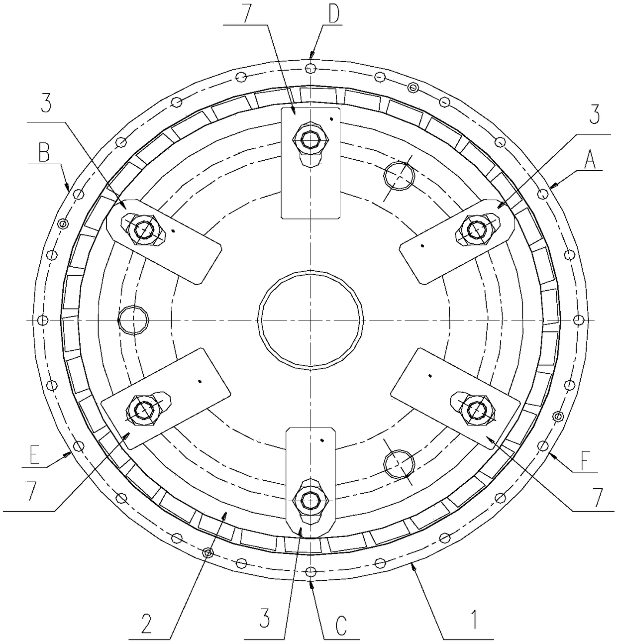
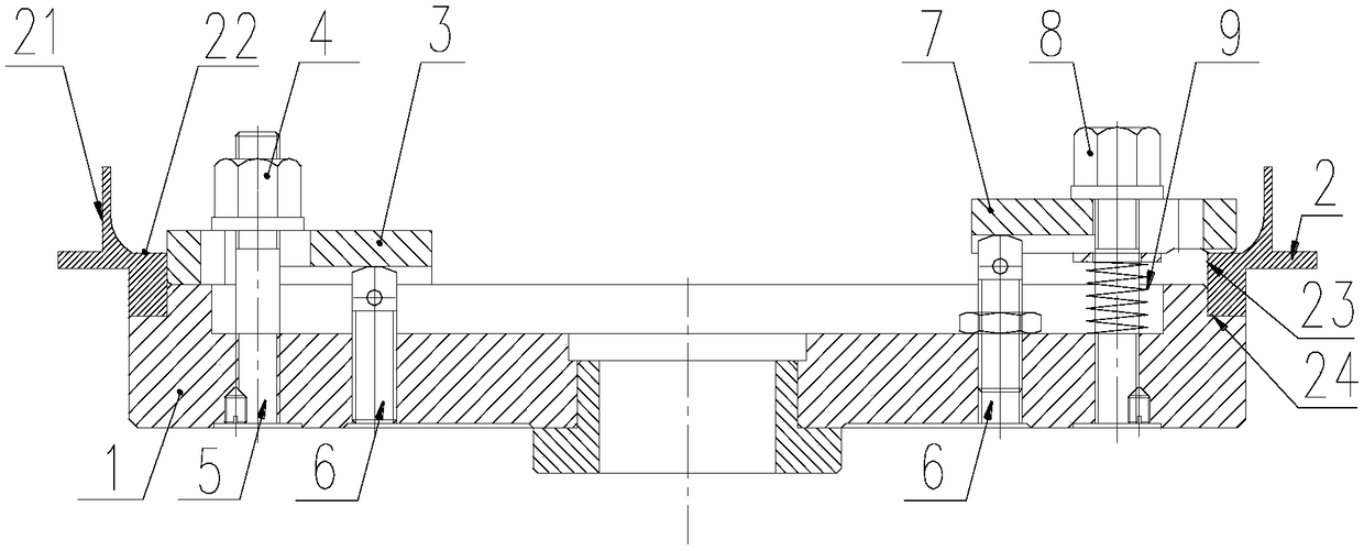
[0028] Reference as figure 1 and figure 2 , a fixture for an annular thin-walled part, which includes a circular fixture support 1 for supporting an annular thin-walled part 2; three stoppers 3 evenly distributed on the fixture support 1 for limiting the The horizontal position of the part 2; three pressure plates 7 that are evenly distributed on the fixture support 1 and spaced from the limit block 3.

[0029] Its structure diagram is as follows image 3 As shown, a circle of steps 11 is arranged on the outermost side of its upper end surface along the circumferential direction, and the step 11 is arranged lower than the upper end surface 12. The bottom end surface 24 and the inner ring surface 23 are positioned; a circular groove is arranged on the upper end surface of the fixture support 1 on the inner side of the step 11, and three thirds are evenly distributed on the circumference of the main body of the fixture support 1 at the lower part of the groove. A threaded h...


PUM


Abstract

The invention discloses an annular thin-wall parts fixture which comprises a cylindrical fixture support, at least three limiting blocks and at least three pressing blocks. An L-symmetrical-shaped step which is not higher than the upper end surface of the cylindrical fixture support is arranged on the outer side of the upper end surface of the cylindrical fixture support along the circumferentialcircle; an annular thin-wall parts is arranged on the step; the limiting blocks are circumferentially and uniformly distributed and fixedly arranged on the fixture support; one ends of the limiting blocks are arranged on the upper end surface of the fixture support; the side surfaces of the ends of the limiting blocks are close to the inner ring surface of the annular thin-wall parts; the pressingblocks and the limiting blocks are fixedly arranged on the fixture support at even intervals; and one ends of the pressing blocks presses the upper end surface of the annular thin-wall parts. The fixture support is used for supporting and limiting, the at least three limiting blocks are used for further limiting, and the at least three pressing blocks are used for pressing, so that the annular thin-wall parts is fixed and clamped and cannot be deformed when the thin-wall outer surface is processed, and the processing quality and the processing efficiency of the annular thin-wall parts are improved.

Description

technical field [0001] The invention belongs to the technical field of machining and clamping, and in particular relates to a fixture for an annular thin-walled part and a method for processing the thin-walled outer surface of the part. Background technique [0002] like Figure 4 and Figure 5 The ring-shaped thin-walled parts in the medium have poor rigidity due to thin wall, such as Image 6 Using B as the support and pressing plate A directly against C will generate a large pressing force. After processing, the annular thin-walled parts will deform and spring back, making it difficult to meet the technical requirements, resulting in unqualified inspection. Contents of the invention [0003] In view of this, the main purpose of the present invention is to provide a fixture for clamping annular thin-walled parts, and to provide a method for processing the thin-walled outer surface of annular thin-walled parts, which solves the problem of using traditional fixtures in th...

Claims


Application Information

Patent Timeline
Patent Type & Authority Applications(China)
IPC IPC(8): B23Q3/00
CPCB23Q3/00B23Q2703/10
Inventor 江昭雄刘春花李伟赵时军
Owner 中国航发湖南南方宇航工业有限公司
Learn More