Atomization assisted CVD film deposition device

A thin film deposition device and mixing chamber technology, applied in the field of thin film manufacturing, can solve the problems of sudden change in airflow field, unavoidable precursor reaction, affecting the quality of thin film film formation, etc., achieve high speed and high quality film formation, and avoid premature reaction. , the effect of reducing costs

Active Publication Date: 2019-02-15
XIDIAN UNIV +1
View PDF5 Cites 2 Cited by
  • Summary
  • Abstract
  • Description
  • Claims
  • Application Information

AI Technical Summary

Problems solved by technology

[0005] 1. The precursor used in CVD is a gas phase. Now there are more academic opinions that the CVD method cannot be directly mixed with a liquid aerosol precursor. In actual use, it is rare to have a liquid phase precursor material input.
[0006] 2. Pyrolytic spraying generally configures the precursor as a solution or a mixed solution and then puts it into the atomization source. After the atomization source is atomized into an aerosol, the liquid aerosol is input into the reaction chamber and pyrolysis occurs in the reaction area, so that The concentration of each component of the precursor cannot be guaranteed, nor can the precursor react in advance, so that the concentration of the precursor solution cannot be guaranteed to be consistent with the concentration of the aerosol liquid particles, and thus the process parameters of the film composition cannot be guaranteed to be credible and repeatable
[0007] 3. The quality of film formation is mainly related to factors such as temperature field, air flow field and precursors. In the prior art, the flat substrate is directly placed on the bottom plane of the reaction zone. We found that the air flow field near the substrate surface in the reaction zone The "distortion" phenomenon will occur due to the thickness of the substrate. The thicker the substrate is, the more significant the "distortion" phenomenon will be, resulting in a sudden change in the airflow field, which will also seriously affect the film quality of the film.

Method used


Image

  • Atomization assisted CVD film deposition device
  • Atomization assisted CVD film deposition device
  • Atomization assisted CVD film deposition device

Examples


Embodiment Construction

[0039] Below in conjunction with accompanying drawing and embodiment the present invention will be further described:

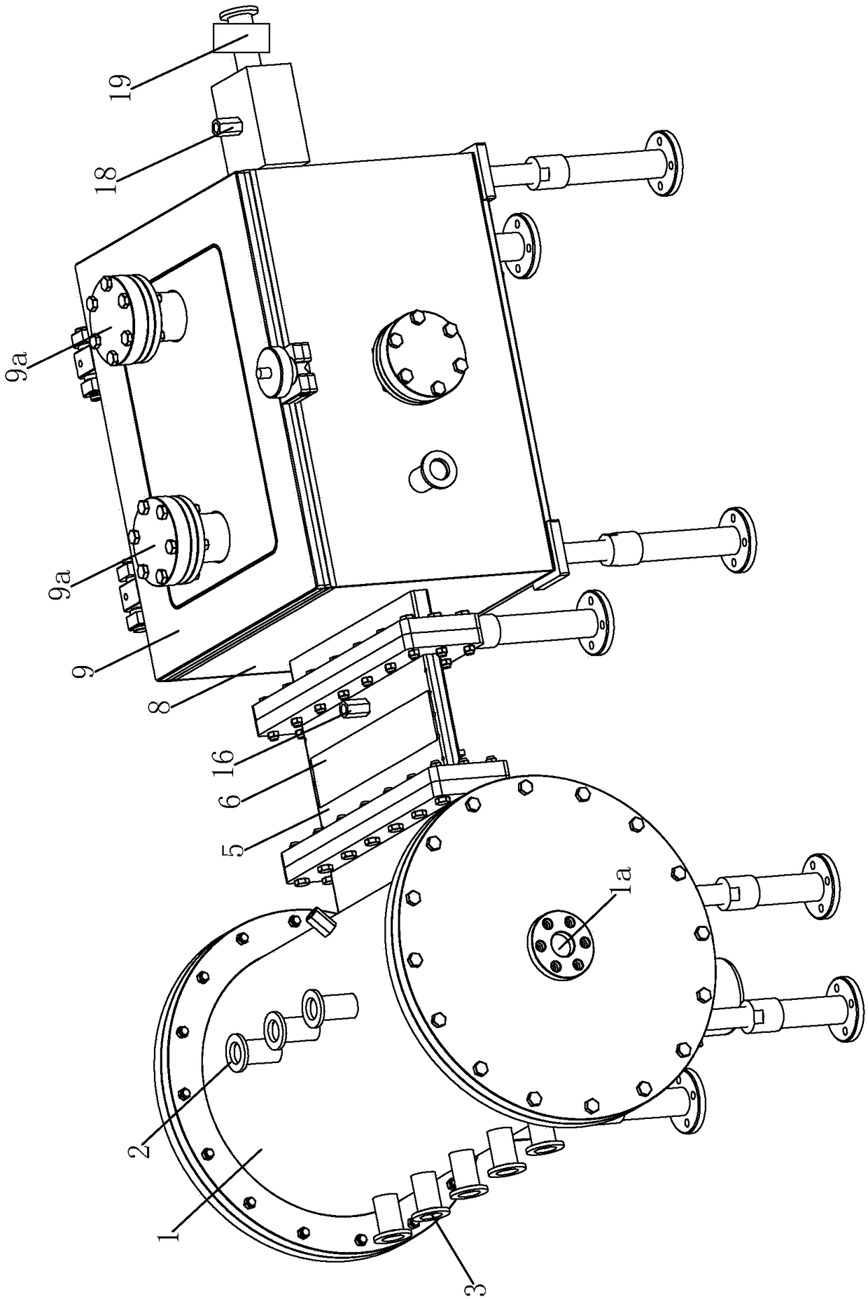
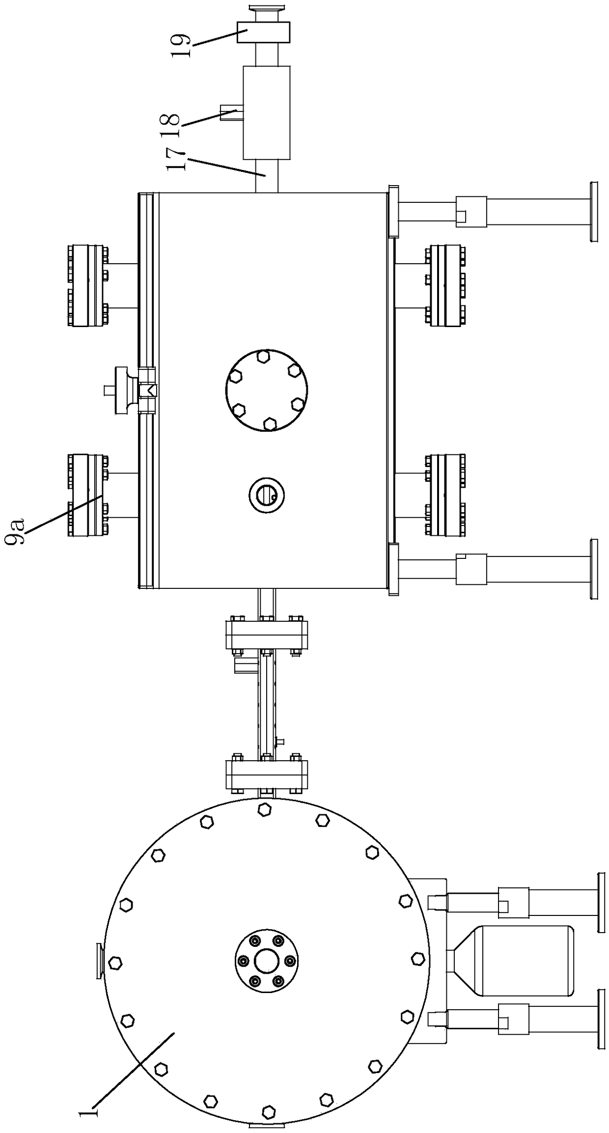
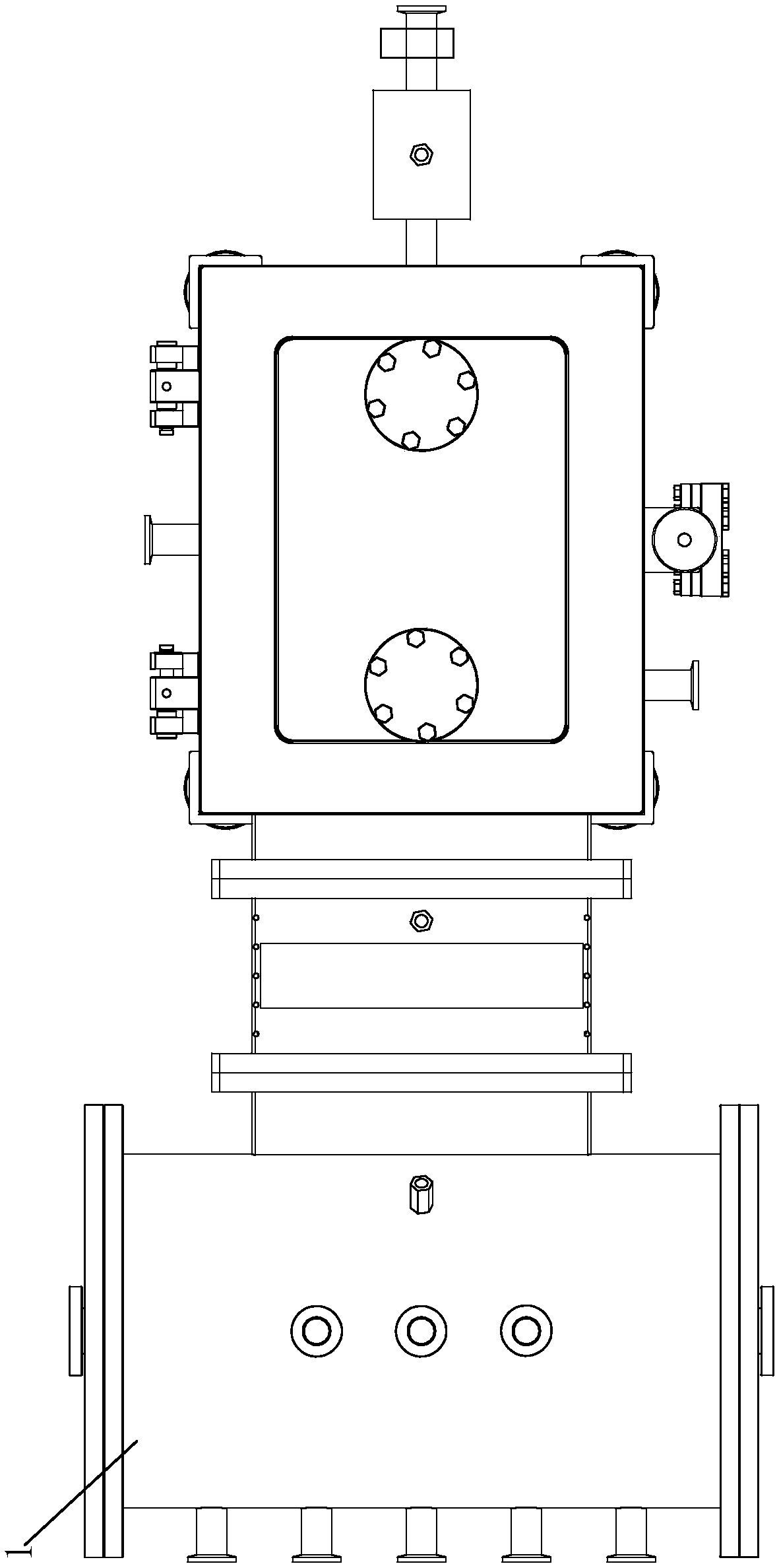
[0040] Such as Figure 1-5 As shown, an atomization-assisted CVD film deposition device is mainly composed of three parts including a buffer mixing chamber 1 , a transition chamber 5 and a reaction chamber 8 . Wherein, the buffer mixing chamber 1 is made of corrosion-resistant material, preferably stainless steel. The top of the buffer mixing chamber 1 is vertically provided with multiple gas-phase material inlet pipes 2. In this case, the number of gas-phase material inlet pipes 2 is three, and they are arranged side by side. In mixing chamber 1. The left side of the buffer mixing chamber wall is provided with multiple aerosol inlet pipes 3. In this case, the number of aerosol inlet pipes 3 is five, and they are arranged side by side. The inlet ends of the aerosol inlet pipe 3 are respectively connected to an independent atomization source (not shown in t...


PUM

PropertyMeasurementUnit
widthaaaaaaaaaa
depthaaaaaaaaaa
heightaaaaaaaaaa

Abstract

The invention discloses an atomization assisted CVD film deposition device. The atomization assisted CVD film deposition device comprises a buffering mixing chamber, a transition cavity and a reactionchamber; the top of the buffering mixing chamber is vertically provided with a plurality of gas phase object inlet pipes; the left side of the outer wall of the buffering mixing chamber is provided with a plurality of aerosol inlet pipes; a set of upper iodine-tungsten filament lamps are fixed to the upper board face of an upper lifting board in the length direction of a reaction cavity side by side; and the left ends and the right ends of the upper lifting board and a lower lifting board are connected with the outer surface of the reaction cavity through two height adjusting assemblies separately, and the heights of the upper lifting board and the lower lifting board can be adjusted under the function of the height adjusting assemblies. According to the scheme, the components and contentof a precursor are ensured mainly from the aspects of a precursor mixing mode and liquid collection, the reaction environment of a reaction area is controlled through the two aspects of ensuring thestability of an airflow field and controlling a temperature field, the technical means of the above four aspects are mutually matched to jointly achieve high-quality film preparation, and the device is especially suitable for manufacturing oxide films.

Description

technical field [0001] The invention belongs to the field of thin film manufacturing, in particular to an atomization-assisted CVD thin film deposition device. Background technique [0002] Thin film materials have a wide range of uses. The existing coating methods mainly include chemical vapor deposition (referred to as CVD) and physical vapor deposition (abbreviated as PVD). There are many sub-categories of coating methods. At present, the precursor of the conventional CVD deposition method is an all-gas phase substance, which is input into the reaction zone of the reaction device to undergo a chemical reaction after being heated or excited by other physical fields, and deposited on the substrate surface, and the CVD method is suitable for preparing high-quality thin films , but the cost is high, the film deposition speed is slow, and most CVD processes need to be carried out in a vacuum environment. The substrate has various structures, such as planar substrate and non-...

Claims


Application Information

Patent Timeline
Patent Type & Authority Applications(China)
IPC IPC(8): C23C18/02C23C16/44
CPCC23C16/44C23C18/02Y02P70/50
Inventor 冯倩龚恒翔郝跃张进成廖飞杨专青马五吉
Owner XIDIAN UNIV
Why Eureka
Try Eureka