Hydraulically driven mechanical powder molding machine

A powder molding machine and driving machinery technology, which is applied in the direction of material molding presses, stamping machines, presses, etc., can solve problems such as complex mechanisms, low powder filling height, and short continuous pressing time

Pending Publication Date: 2019-02-19
南通力友液压机制造有限公司
View PDF0 Cites 0 Cited by
  • Summary
  • Abstract
  • Description
  • Claims
  • Application Information

AI Technical Summary

Problems solved by technology

But at the same time, there are shortcomings of short continuous pressing time and low powder filling height, which are difficult to overcome; the forming efficiency of hydraulic press is low, and the pressed products are limited by oil temperature and hydraulic principle, and the product size fluctuates greatly.
However, the powder filling heigh

Method used


Image

  • Hydraulically driven mechanical powder molding machine
  • Hydraulically driven mechanical powder molding machine
  • Hydraulically driven mechanical powder molding machine

Examples


Embodiment Construction

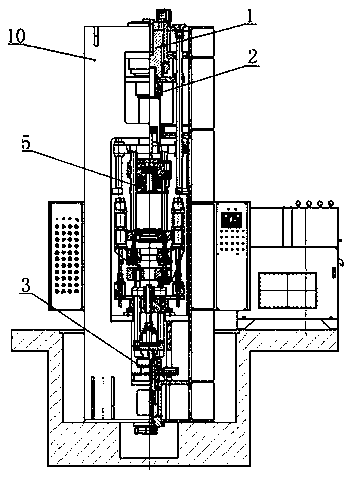
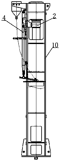
[0041] Reference attached figure 1 , Hydraulically driven mechanical powder molding machine, which includes body 10, upper limit cylinder 1, screw adjustment structure 2, lower cylinder structure 3, feeding mechanism 4 and mold base assembly 5. The body 10 is a frame body, the body 10 The upper limit oil cylinder 1, the screw rod adjustment structure 2, the mold base assembly 5, and the lower oil cylinder structure 3 are sequentially installed in the middle from top to bottom. The feeding mechanism 4 is installed on the side of the body 10, and the upper limit oil cylinder 1 is connected to the screw rod adjustment structure. 2. The lower end of the screw rod adjustment structure 2 is connected to the mold base assembly 5, and the lower end of the mold base assembly 5 is connected to the lower cylinder structure 3.

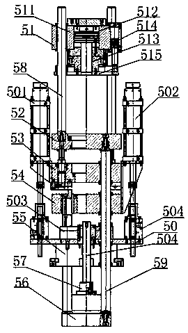
[0042] Such as Figure 2-5 , The die set assembly 5 includes a double upper punch 51, a female template 52, a lower punch 53, a lower two punch 54, a fixed punch 55, ...


PUM


Abstract

The invention relates to a hydraulically driven mechanical power molding machine. The hydraulically driven mechanical power molding machine comprises a machine body, an upper limiting oil cylinder, alead screw adjusting structure, a lower oil cylinder structure, a feed mechanism and a formwork assembly. The machine body is a frame machine body. The upper limiting oil cylinder, the lead screw adjusting structure, the formwork assembly and the lower oil cylinder structure are sequentially arranged on the middle of the machine body from top to bottom. The feed mechanism is arranged on one side of the machine body. The upper limiting oil cylinder is connected to the lead screw adjusting structure. The lower end of the lead screw adjusting structure is connected to the formwork assembly. The lower end of the formwork assembly is connected to the lower oil cylinder structure. The hydraulically driven mechanical power molding machine has the characteristics of simple structure, reliable operation, high automation, and convenient mould installation. The hydraulically driven mechanical power molding machine further has advantages of high efficiency, high powder loading, stable product compression and the like. Quickly pressing powder metallurgy parts at a lower cost in the powder metallurgy industry of China becomes possible.

Description

Technical field [0001] The invention relates to the field of powder molding machines, in particular to a hydraulically driven mechanical powder molding machine. Background technique [0002] At present, there are basically two types of powder molding machines, one is a mechanical powder molding machine, and the other is a hydraulic molding machine, which is driven by a crankshaft and a cylinder respectively. The actions are multi-axis linkage and series single cycle. The mechanical press has the advantages of high efficiency and stable size of the batch pressed products. But at the same time, there are the shortcomings of short continuous pressing time and low powder filling height, which are difficult to overcome; the forming efficiency of hydraulic press is low, and the pressed product is limited by the oil temperature and hydraulic principle, and the product size fluctuates greatly. However, the height of the powder filling of the hydraulic press is not limited, the pressure...

Claims


Application Information

Patent Timeline
IPC IPC(8): B30B11/04B30B15/02B30B15/30B30B15/32B30B1/32
CPCB30B11/027B30B1/32B30B11/04B30B15/02B30B15/026B30B15/30B30B15/32
Inventor 孙丰
Owner 南通力友液压机制造有限公司
Why Eureka
Try Eureka