Rotary biofilm reactor

A biofilm reactor, rotary technology, applied in biological treatment devices, sustainable biological treatment, biological water/sewage treatment, etc., can solve the problem of membrane flux decline, reduce energy consumption, reduce aeration volume and aeration time and other issues, to achieve the effect of efficient handling

Pending Publication Date: 2019-02-19
CLEAR SUZHOU ENVIRONMENTAL TECH CO LTD
View PDF1 Cites 2 Cited by
  • Summary
  • Abstract
  • Description
  • Claims
  • Application Information

AI Technical Summary

Problems solved by technology

[0005] (1) Membrane flux decline due to membrane surface concentration polarization and fouling;
[0006] (2) The membrane cleaning process is complicated and the operation is cumbersome;
[0007] (3) Too much aeration, high energy consumption
[0008] For example, a floating rolling biofilm reactor disclosed in the Chinese patent with the application number "201510353993.7", in the structure disclosed in the above patent, it mainly includes a rotating shaft, a biological filler cage, and several escalators and cables; The combination of the activated sludge method of flaunting rich growth and the biofilm method of attached growth can reduce the aeration volume and aeration time to a certain extent, and reduce energy consumption; however, during the treatment process, the overall water flow is relatively static, so for corners or certain Some locations cannot be adequately aerated

Method used


Image

  • Rotary biofilm reactor
  • Rotary biofilm reactor
  • Rotary biofilm reactor

Examples


Embodiment 1

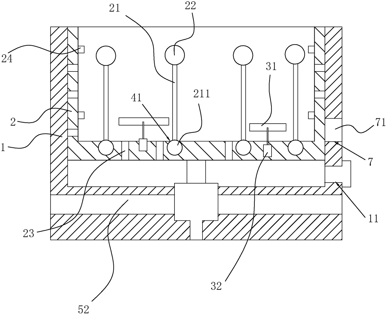
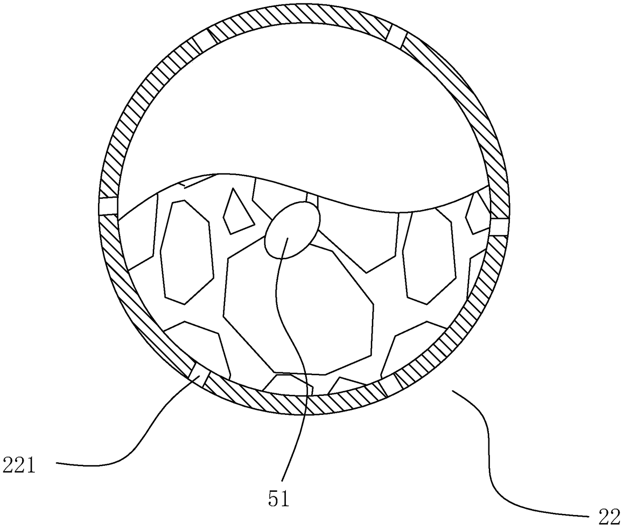
[0029] A rotary biofilm reactor, such as figure 1 As shown, it includes an outer frame 1 and a reaction chamber 2. The outer frame 1 and the reaction chamber 2 are nested with each other, and a lifting device is provided between the two. The reaction chamber 2 and the outer frame 1 can be separated by using the lifting device. The lifting device includes a groove 61 formed from the bottom of the outer frame 1 and a cylinder 62 arranged in the groove 61. The piston rod of the cylinder 62 is connected to the bottom of the reaction chamber 2, and a hole may be provided at the bottom of the groove 61 for the cylinder. 62 communicates with the outside world, but sealing measures need to be taken at the hole; some fixed rods 21 are arranged in the reaction chamber 2, and each fixed rod 21 is provided with a biological filler cage 22, and the reaction chamber 2 is provided with a number of holes penetrating through its thickness. The through hole 23 also includes a connection device ...


PUM


Abstract

The invention relates to a rotary biofilm reactor. The reactor comprises an outer frame and a reaction cavity which are arranged through mutual sleeving; multiple fixed rods are arranged in the reaction cavity, each fixed rod is provided with a biological packing cage, and multiple through holes running through the thickness of the reaction cavity are formed in the reaction cavity; the reactor further comprises a connecting device capable of making the biological packing cages move in all directions. When the device is utilized for conducting sewage treatment, the reaction cavity can be liftedto be separated from the outer frame through a lifting device, then water is injected inside by means of a water inlet, and then the reaction cavity is put into the outer frame through the lifting device; in the putting process, water flows into the reaction cavity through the through holes; then a driving motor is turned on, a stirring paddle rotates, the positions of all the biological packingcages are adjusted, the biological packing cages are uniformly located in the reaction cavity, and then the problem that in the background technology, a reaction of partial water areas is insufficientis avoided.

Description

technical field [0001] The invention relates to a biofilm reactor, in particular to a rotary biofilm reactor. Background technique [0002] Membrane bioreactor (Membrane io-Reactor, MBR) is a new type of wastewater treatment system that organically combines membrane separation technology and biological treatment technology. Replace the terminal secondary sedimentation tank of traditional biological treatment technology with membrane modules, maintain a high concentration of activated sludge in the bioreactor, increase the organic load of biological treatment, thereby reducing the footprint of sewage treatment facilities, and reduce the remaining sewage by maintaining low sludge load amount of mud. [0003] Activated sludge and macromolecular organic matter in water are mainly retained by membrane separation equipment, and the concentration of activated sludge (MLSS) in the membrane bioreactor system can be increased to 8000-10,000mg / L, or even higher; the sludge age (SRT) c...

Claims


Application Information

Patent Timeline
Patent Type & Authority Applications(China)
IPC IPC(8): C02F3/12
CPCC02F3/1268C02F2203/006Y02W10/10
Inventor 曹俊刘玲子
Owner CLEAR SUZHOU ENVIRONMENTAL TECH CO LTD
Why Eureka
Try Eureka