Electric field-assisted ceramic material sintering furnace and control method thereof

A ceramic material, electric field assisted technology, used in furnace control devices, electric furnace heating, furnaces, etc., can solve the problems of high sintering temperature, high energy consumption, long sintering time, etc., to reduce the sintering temperature of ceramics, achieve densification, and save energy. The effect of loss

Inactive Publication Date: 2019-02-19
CHANGAN UNIV
7 Cites 9 Cited by

AI-Extracted Technical Summary

Problems solved by technology

[0004] Aiming at the deficiencies of the existing technology, the object of the present invention is to provide a ceramic material sintering furnace and its control method assi...

Method used

Concrete, the near end of described two sections pipe body 21 is respectively provided with a protruding part 22 and the recessed part 23 that matches with this protruding part 22, and the opposite surface of described protruding part 22 and recessed part 23 Electrodes 6 are respectively provided on them. When in use, the sample is placed in the recessed part 23, and then the protruding part 22 is extended into the recessed part 23 to withstand the sample. The design of the protruding part 22 and the recessed part 23 makes it easier to place the samples to be processed, and also ensures the connection of the entire circuit.
[0040] Preferably, the wire ...

Abstract

The invention provides an electric field-assisted ceramic material sintering furnace and a control method thereof. The sintering furnace comprises a tubular furnace, a clamping device, an electric field application module and a data observation and recording module; the clamping device comprises two pipe bodies; the two ends of the two pipe bodies are sealed and are arranged in the two ends of thetubular furnace respectively through corresponding supporting devices; the opposite ends of the two pipe bodies are each provided with an electrode; and one electrode, the data observation and recording module, the electric field application module and the other electrode are sequentially connected in series through wires. The pipe bodies with conducting parts are arranged in the two ends of thetraditional tubular furnace. During the sintering process, an external electric field is applied, so that the sintering densification process of ceramic material can be greatly promoted, then low-temperature flash sintering of the ceramic material, namely, the densification of the ceramic material within dozens of seconds at low temperature is realized; and the sintering temperature of ceramics isfinally reduced, the sintering time of the ceramics is shortened, and the energy loss is greatly saved.

Application Domain

Furnace typesElectric heating for furnaces +1

Technology Topic

Tube furnaceElectric field +5

Image

  • Electric field-assisted ceramic material sintering furnace and control method thereof
  • Electric field-assisted ceramic material sintering furnace and control method thereof
  • Electric field-assisted ceramic material sintering furnace and control method thereof

Examples

  • Experimental program(4)

Example Embodiment

[0051] Example 1:
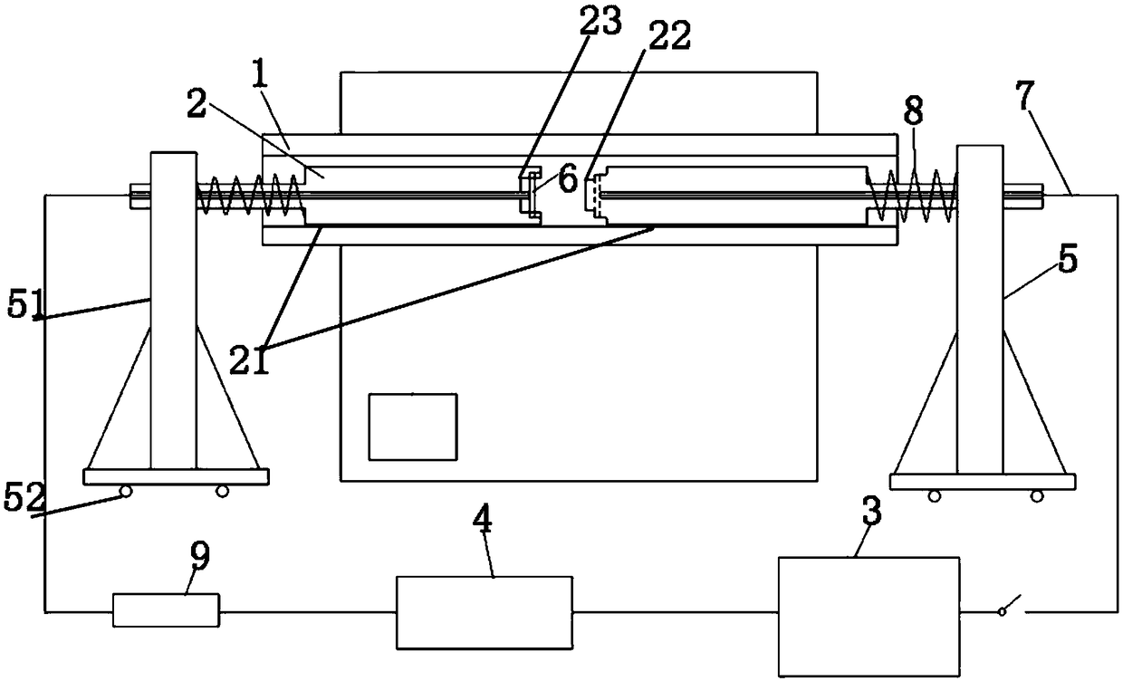
[0052] This embodiment provides a ceramic material sintering furnace assisted by an electric field, which includes a tube furnace 1 with a shell on the outside, and a time and furnace temperature control unit on the shell. The tube furnace can be realized through the time and furnace temperature control unit. According to the presetting of the heating program of the body, the prepared PZT ceramic powder is uniaxially pressed into a cylindrical shape, and the two ends are coated with platinum slurry for use. Put the PZT ceramic sample coated with platinum paste on the front end of the alumina ceramic tube 2 on one side, and a platinum sheet 6 is installed at the front end, and lightly stick the sample on the platinum sheet 6, and the platinum wire 7 passes through the ceramic tube 2 and the platinum sheet 6 connected, the other end stretches out the ceramic tube 2, the spring 8 is placed between the ceramic tube 2 and the support frame 51, one end is against the step of the ceramic tube 2, the other end is against the support frame 51, and the bottom of the support frame 51 has a belt The pulley 82 of lock buckle. After the sample is placed, slowly push the supporting frames 51 on both sides, and the elastic force of the spring 8 and the matching protrusion 22 and recess 23 at the front end of the ceramic tube 2 clamp the sample in the center and keep the electrodes in stable contact. Place an external circuit protection device 9 on the outside, connect to a suitable protection resistor 200Ω, connect to the data observation and recording module 4 on the right side of the external circuit protection device 9, and connect to the electric field application device 3 on the right side of the data observation device 9 , and then connect the two ends of the circuit connected in series with the platinum wires 7 protruding from the ceramic tubes 2 on both sides to complete the connection of the entire circuit.
[0053] During work, the setting of the heating program is completed through the time and temperature control unit 3 . Set the initial temperature as room temperature, and the heating rate as 10°C/min. The voltage and maximum current output parameters are set through the electric field application device 3, wherein the output voltage is 1000V, and the limit current is 100mA. After the setting is completed, the tube furnace 1 and the electric field application device 3 are started to realize the electric field assisted sintering of the PZT ceramic sample. Pay attention to the readings on the data observation and recording module 4 during sintering. When the furnace temperature is 500°C, the current rises rapidly to reach the limit current. Keep sintering in this state for 30s, and then close the sintering device. Figure 4 SEM photos of PZT prepared by sintering under this condition, it can be seen that the sample has achieved complete densification. Compared with the traditional sintering method, with the sintering furnace provided by the present invention, the sintering temperature of the PZT ceramic material is reduced by about 400°C, and the sintering time is reduced from several hours to 30s.

Example Embodiment

[0054] Example 2:
[0055] This embodiment provides a ceramic material sintering furnace assisted by an electric field. The difference between this embodiment and Embodiment 1 is that the sample to be processed is made of Al 2 o 3 For ceramic materials, the applied voltage is set to 1400V through the electric field applying device 3, and the final furnace temperature is 1400°C.
[0056] Figure 5 Al is prepared for sintering under this condition 2 o 3 From the SEM photo of the ceramic, it can be seen that the sample has been completely densified. Compared with the traditional sintering method, adopting the sintering furnace provided by the present invention, Al 2 o 3 The sintering temperature of the ceramic material is reduced by about 300°C, and the sintering time is reduced from several hours to 30s.

Example Embodiment

[0057] Example 3:
[0058] This embodiment provides a ceramic material sintering furnace assisted by an electric field. The difference between this embodiment and Embodiment 1 is that the sample to be processed is made of KNN ceramic material, and the applied voltage is set to 1400V by the electric field application device 3, and the final furnace temperature is 750°C.
[0059] Image 6 SEM photos of KNN ceramics prepared by sintering under this condition, it can be seen that the samples are completely densified. Compared with the traditional sintering method, with the sintering furnace provided by the present invention, the sintering temperature of the KNN ceramic material is reduced by about 300°C, and the sintering time is reduced from several hours to 30s.

PUM

no PUM

Description & Claims & Application Information

We can also present the details of the Description, Claims and Application information to help users get a comprehensive understanding of the technical details of the patent, such as background art, summary of invention, brief description of drawings, description of embodiments, and other original content. On the other hand, users can also determine the specific scope of protection of the technology through the list of claims; as well as understand the changes in the life cycle of the technology with the presentation of the patent timeline. Login to view more.

Similar technology patents

Continuous slurry polymerization volatile removal

InactiveUS6858682B2increase ethylene concentrationreduce energy consumption
Owner:EXXONMOBIL CHEM PAT INC

Wireless sensor network node device used in underground coal mine

InactiveCN101621431AReduce energy consumptionextended life cycle
Owner:CHINA UNIV OF MINING & TECH
Why Eureka
Try Eureka