A Novel Sputtering Ion Pump for Anode Barrel Array

An anode cylinder and ion pump technology, applied in the field of sputtering ion pump, can solve problems such as low pumping speed, and achieve the effects of simple structure, long service life and wide working pressure range

Active Publication Date: 2020-05-26
NORTHEASTERN UNIV LIAONING
View PDF2 Cites 0 Cited by
  • Summary
  • Abstract
  • Description
  • Claims
  • Application Information

AI Technical Summary

Problems solved by technology

[0004] The present invention aims at the defect of low pumping speed of existing sputtering ion pumps in an ultra-high vacuum environment, and provides a new type of sputtering ion pump with an array of anode cylinders

Method used


Image

  • A Novel Sputtering Ion Pump for Anode Barrel Array
  • A Novel Sputtering Ion Pump for Anode Barrel Array
  • A Novel Sputtering Ion Pump for Anode Barrel Array

Examples


Embodiment Construction

[0022] It should be noted that all directional indications (such as up, down, left, right, front, back...) in the embodiments of the present invention are only used to explain the relationship between the components in a certain posture (as shown in the accompanying drawings). Relative positional relationship, movement conditions, etc., if the specific posture changes, the directional indication will also change accordingly.

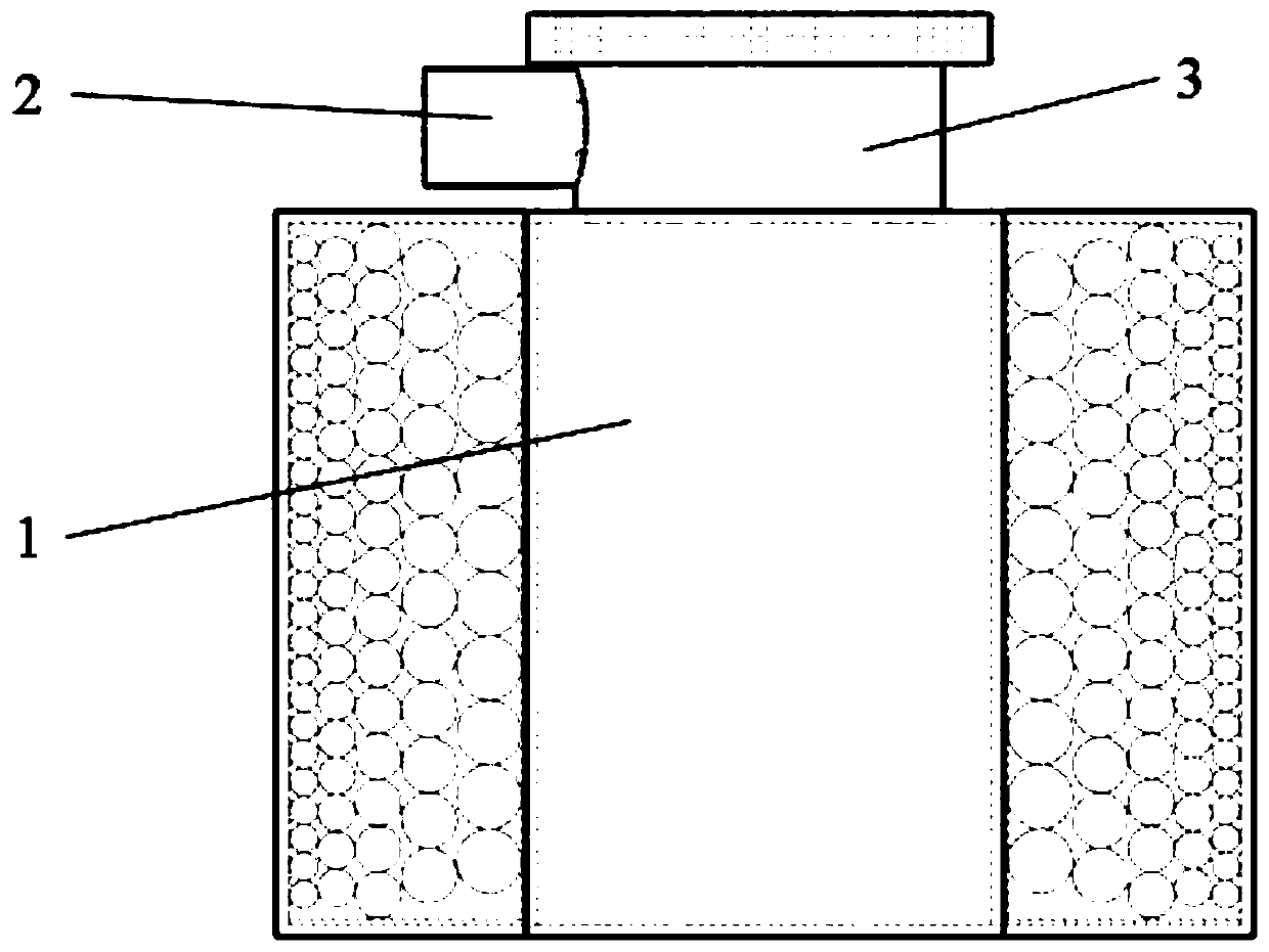
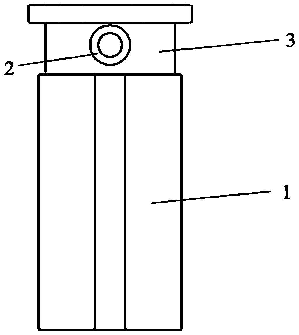
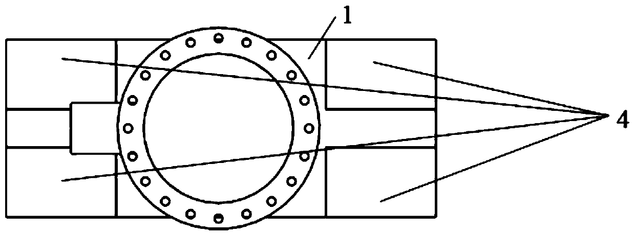
[0023] Such as Figure 1 to Figure 6 As shown, the present invention provides a sputtering ion pump with a novel anode cylinder array, which includes a casing 1 , a high voltage electrode 2 , a cathode plate 5 and an anode cylinder array 6 .

[0024] The shell 1 is a rectangular column structure, and its material is mainly 316 stainless steel. The top of the shell 1 is provided with an air inlet 3. The air inlet 3 is processed by stamping. It is a cylindrical pipe structure, and its material is mainly 316 stainless steel. Stainless steel, the gas flows ...


PUM

PropertyMeasurementUnit
thicknessaaaaaaaaaa

Abstract

The invention discloses a novel sputter ion pump with a positive electrode barrel array. The novel sputter ion pump is characterized by comprising a shell; a gas inlet is formed in the top of the shell, magnets are mounted on the left side and the right side of the shell, the positive electrode barrel array is mounted inside the shell in an insulation manner, negative electrode plates are arrangedon two sides of the positive electrode barrel array, a high-voltage electrode and the gas inlet are fixedly assembled, positive potential of the high-voltage electrode is connected with the positiveelectrode barrel array, zero potential of the high-voltage electrode is connected with the two negative electrode plates, chambers for exhausting gas are formed between the negative electrode plates and the positive electrode barrel array, the positive electrode barrel array comprises a plurality of groups of positive electrode barrels, the radiuses of the positive electrode barrels are increasedalong with decrease of the distances from the positive electrode barrels to the gas inlet, the heights of the positive electrode barrels are decreased along with decrease of the distances from the positive electrode barrels to the gas inlet, and the sizes of gaps between the upper and lower surfaces of the positive electrode barrels and the negative electrode plates are increased along with decrease of the distances from the positive electrode barrels to the gas inlet; the radiuses of the positive electrode barrels are decreased along with increase of the distances from the positive electrodebarrels to the gas inlet, the heights of the positive electrode barrels are increased along with increase of the distances from the positive electrode barrels to the gas inlet, and the sizes of the gaps between the upper and lower surfaces of the positive electrode barrels and the negative electrode plates are decreased along with increase of the distances from the positive electrode barrels to the gas inlet. The novel sputter ion pump has the advantages that the gas exhaust speed in unit volume of the novel sputter ion pump can be greatly increased, and the novel sputter ion pump can keep working at the high exhaust speed even in ultrahigh-vacuum environments.

Description

technical field [0001] The invention belongs to the technical field of vacuum acquisition, and in particular relates to a sputtering ion pump of a novel anode cylinder array. Background technique [0002] The sputtering ion pump was named in the 1950s and the corresponding theory was put forward. It maintains pumping through the Penning discharge principle, and then obtains an ultra-high vacuum environment. It is characterized by zero noise, no vibration, no oil pollution in the pump cavity, simple and firm structure, long service life, no need for refrigerant, wide working pressure range, which can be between 1 and 10 -10 Working in the range of Pa, it is a clean vacuum pump. Its working process is divided into two parts. The first is the Penning discharge process. The electrons in the pump chamber collide with the gas molecules under the action of the electromagnetic field to ionize the gas molecules. The second is the gas capture process. The cations produced bombard th...

Claims


Application Information

Patent Timeline
Patent Type & Authority Patents(China)
IPC IPC(8): H01J41/12H01J37/18
CPCH01J37/18H01J41/12
Inventor 王晓冬宁久鑫黄海龙田野
Owner NORTHEASTERN UNIV LIAONING
Why Eureka
Try Eureka