Steel bar straightening machine

A technology for straightening machines and steel bars, which is applied in the field of wheel hub bearings, can solve the problems of inability to effectively straighten universally twisted steel bars, inconvenient straightening of steel bars for automatic feeding of steel bars, and unsatisfactory straightening effects, etc. Small friction, improve the effect of elimination

Pending Publication Date: 2019-02-22
重庆宏扬电力器材有限责任公司
View PDF20 Cites 11 Cited by
  • Summary
  • Abstract
  • Description
  • Claims
  • Application Information

AI Technical Summary

Problems solved by technology

The current common straightening methods are: 1), use horizontal and vertical pressure rollers to straighten the steel bars, this method cannot effectively straighten the universally twisted steel bars; 2), use the rotating frame to set the rollers to straighten the steel bars , this method is disclosed in the patent document "CN200520102272.9-straightening roller device", and the rollers in the rotating frame can be used to effectively straighten the steel bars in multiple directions, but this method automatically feeds the steel bars and different wire diameters It is inconvenient to straighten the steel bars, and the straightening effect is not ideal

Method used


Image

  • Steel bar straightening machine
  • Steel bar straightening machine
  • Steel bar straightening machine

Examples


Embodiment Construction

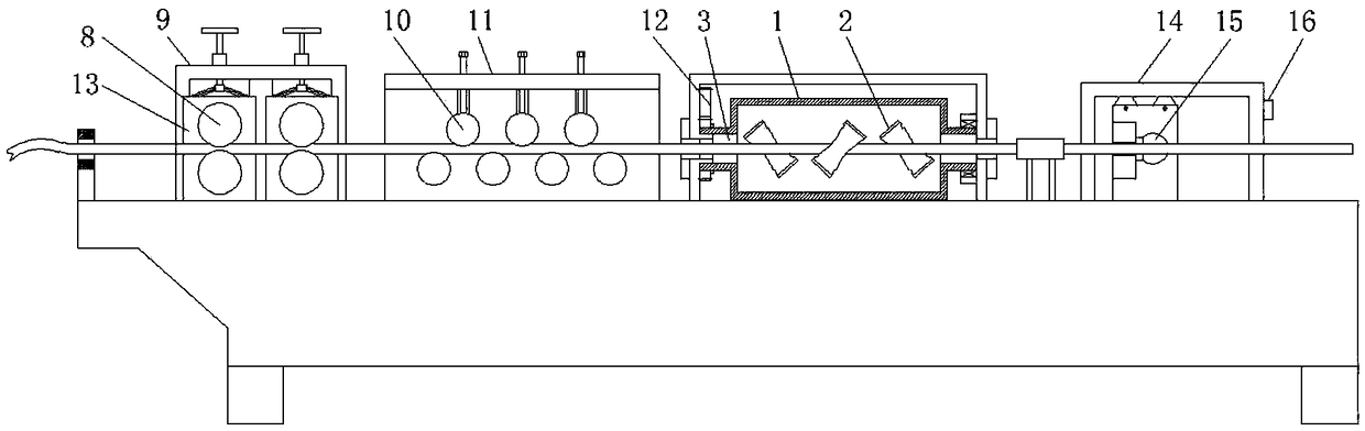
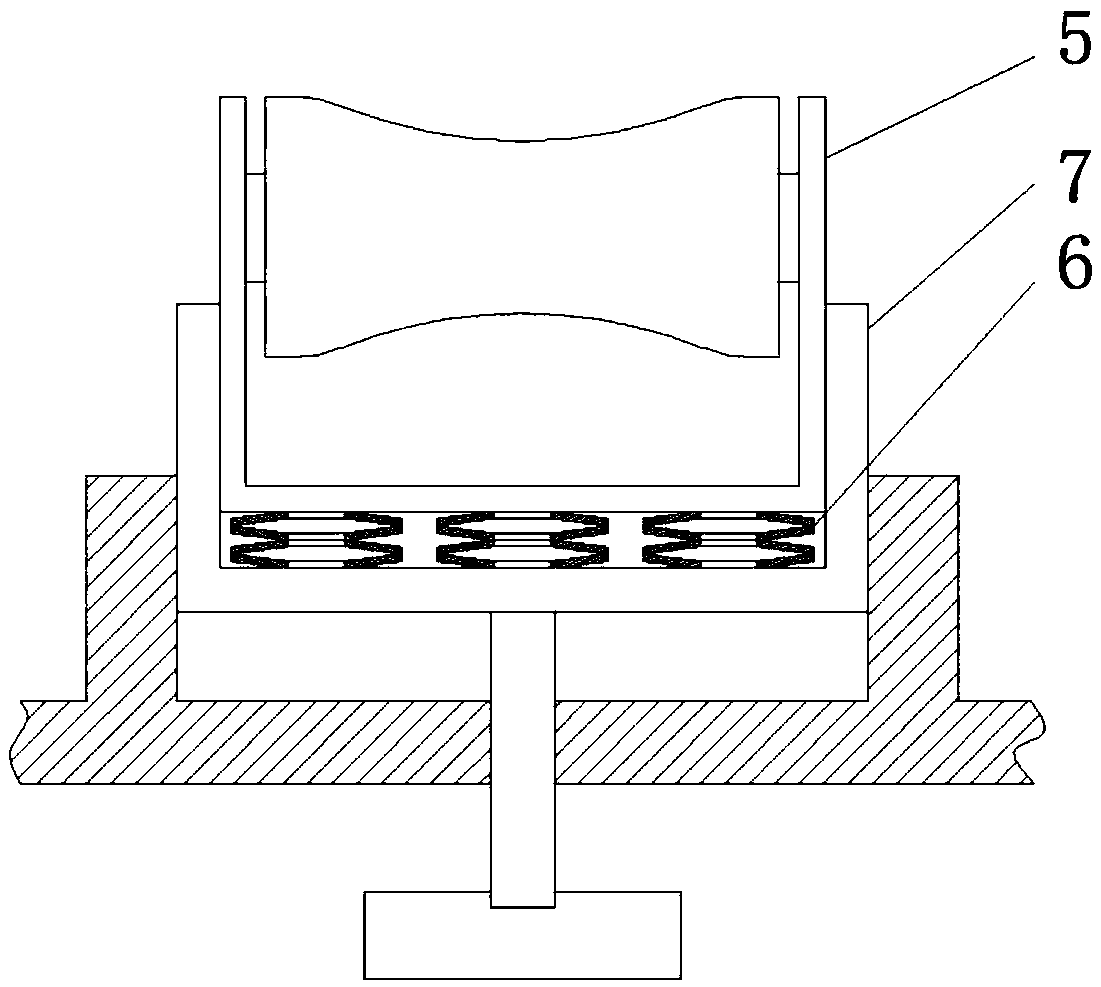
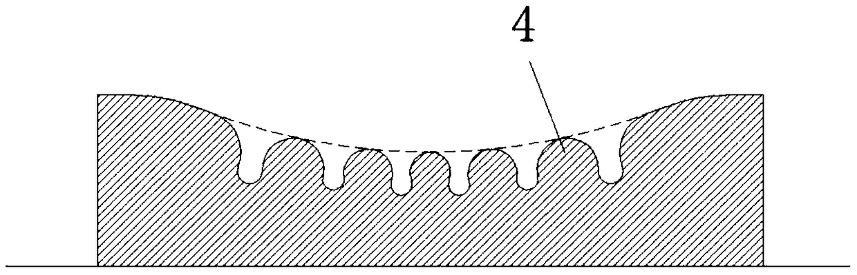
[0022] figure 1 It is a structural schematic diagram of the present invention; figure 2 It is a schematic diagram of the inclined roller structure; image 3 is a schematic diagram of the bump structure;

[0023] As shown in the figure: it includes a straightening cylinder 1 and several inclined rollers 2 arranged in the straightening cylinder for eliminating the internal stress of the steel bars. The two ends of the straightening cylinder 1 are coaxially provided with openings 3 for the entry and exit of steel bars. The oblique rollers 2 are alternately arranged on both sides of the radial direction of the steel bar and are used to cooperate with the outer surface of the steel bar to roll. The axes of the oblique rollers 2 and the axis of the straightening cylinder 1 are arranged at an angle. The hemispherical contact protrusion 4 protrudes outward along its radial direction. The radius of the contact protrusion 4 gradually increases from the axial middle of the inclined ro...


PUM


Abstract

The invention discloses a steel bar straightening machine. The steel bar straightening machine straightening cylinder and a plurality of inclined rolling wheels which are arranged in the straighteningcylinder and are used for eliminating internal stress of a steel bar, the multiple inclined rolling wheels are arranged on the two radial sides of the steel bar in a staggered mode, the axis of the inclined rolling wheels is arranged at an angle with the axis of the straightening cylinder, the outer peripheral surfaces of the inclined rolling wheels are provided with hemispherical touch protrusions which protrude outwards in the radial direction of the inclined rolling wheels, the axial middle of the inclined rolling wheels is gradually increased towards the radius of the contact protrusionsat the two ends of the inclined rolling wheels, the contact protrusions distributed on the outer peripheral surfaces of the inclined rolling wheels are externally cut into inwards-concave annular cutting surfaces, and the annular sections are arranged coaxial with the inclined rolling wheels. According to the steel bar straightening machine, the internal stress of the steel bar is eliminated through interaction of multiple points with different friction force and torque; and by correction of the multiple inclined rolling wheels located on the two sides of the steel bar, the stress in the steelbar reaches a stress balance state, and the straightening effect of the steel bar is improved.

Description

technical field [0001] The invention belongs to the technical field of hub bearings, in particular to a steel bar straightening machine. Background technique [0002] At present, steel members used in the fields of construction engineering or machinery manufacturing are usually first cut by straightening and cutting the disc-shaped steel bars produced by the steel factory, and then bent into the required shape before application. The current common straightening methods are: 1), use horizontal and vertical pressure rollers to straighten the steel bars, this method cannot effectively straighten the universally twisted steel bars; 2), use the rotating frame to set the rollers to straighten the steel bars , this method is disclosed in the patent document "CN200520102272.9-straightening roller device", and the rollers in the rotating frame can be used to effectively straighten the steel bars in multiple directions, but this method automatically feeds the steel bars and different...

Claims


Application Information

Patent Timeline
Patent Type & Authority Applications(China)
IPC IPC(8): B21F1/02B21F11/00B21C51/00
CPCB21C51/00B21F1/026B21F11/00
Inventor 洪伟洪敏李兴义蒋亚铭李燕燕杨杰
Owner 重庆宏扬电力器材有限责任公司
Why Eureka
Try Eureka