An unsteady flow visualization method for an aero-engine compressor

An unsteady flow and aero-engine technology, which is applied in the field of aviation aircraft, can solve problems affecting the authenticity of the flow field, display, and inflexibility, and achieve the effects of reducing labor costs and time costs, improving analysis efficiency, and reducing manual operations

An unsteady flow and aero-engine technology, which is applied in the field of aviation aircraft, can solve problems affecting the authenticity of the flow field, display, and inflexibility, and achieve the effects of reducing labor costs and time costs, improving analysis efficiency, and reducing manual operations

CN109409016AActive Publication Date: 2019-03-01CALCULATION AERODYNAMICS INST CHINA AERODYNAMICS RES & DEV CENT

Image

  • An unsteady flow visualization method for an aero-engine compressor
  • An unsteady flow visualization method for an aero-engine compressor

Examples


Embodiment Construction

[0032] A visualization method for the unsteady flow of an aeroengine compressor, such as figure 1 shown, including the following steps:

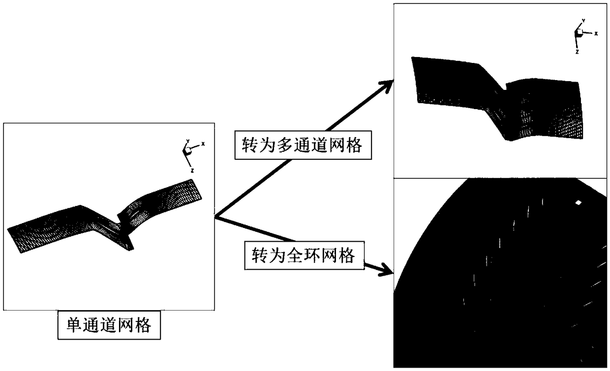
[0033] Step 1. Use commercial software such as NUMECA or Pointwise to generate multi-block structured grids of single-blade passages of multi-stage compressors. In this way, the amount of grids that need to be generated is small and the generation speed is fast, which greatly reduces tedious manual operations. The computer's memory requirements are also low.

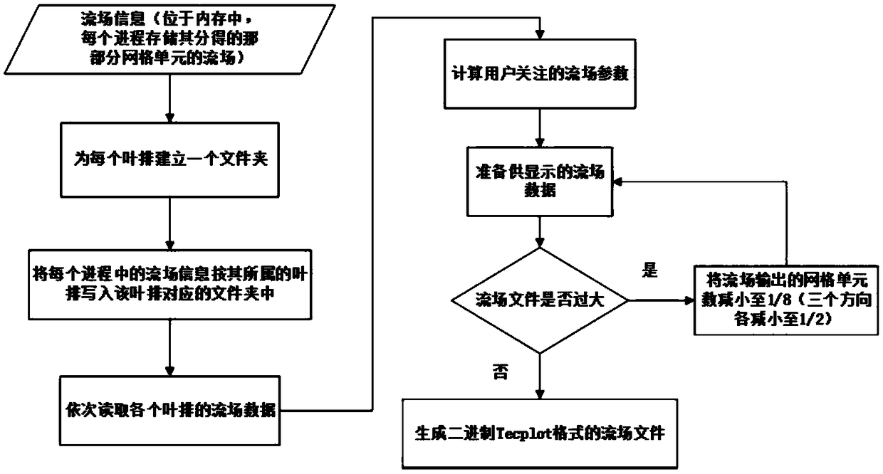
[0034] Step 2. Generate the full-ring mesh of the axial flow compressor through the software SCTMC, take the single-channel mesh as input, and output the full-ring mesh after processing such as rotation and determination of the docking relationship, and mark the compressor blade where each mesh block is located. Row. Since the size of the full-ring grid data file can reach tens of GB, this step can be performed on a supercomputer without manual intervention and without considering th...


PUM


Abstract

The invention discloses an aero-engine compressor unsteady flow visualization method which comprises the following steps: taking a single-channel grid as an input / output full-ring grid, and marking acompressor blade row where each grid block is located; Distributing all the grid blocks to different processes, independently outputting the flow field on the distributed grid blocks by each process when the flow field is stored, and establishing a folder for each leaf row; sequentially reading the flow field data of each blade row, and calculating flow field parameters; and outputting a flow field visualization file according to the interface standard of the visualization software Tecplot. The system has the capability of visualizing unsteady mass flow field data of the multi-stage compressoron a single machine; the multi-stage compressor has the capability of extracting and independently processing any blade row in the multi-stage compressor; the method has the capability of automatically extracting the two-dimensional tangent plane and the capability of reducing the size of the flow field file by about one order of magnitude.

Description

technical field [0001] The invention relates to an unsteady flow visualization method of an aero-engine compressor, which belongs to the technical field of aero-vehicles. Background technique [0002] In the design and modification process of aero-engine compressors, multiple compressor geometric shapes are available for selection. At this time, it is necessary to evaluate the global aerodynamic performance and internal flow details of different shapes to provide reference for model selection. The internal flow details of the compressor are extremely rich, among which the tip leakage flow, corner flow, unsteady interference between blade rows, blade pressure distribution, shock wave / boundary layer interference on the blade directly affect the local performance of the compressor blade, And indirectly affect the overall aerodynamic performance of the compressor. Through the visualization of compressor flow details, these flow details can be evaluated intuitively. [0003] At...

Claims


Application Information

Patent Timeline
01 Mar 2019
Publication
CN109409016A
IPC
G06F17/50
CPC
G06F30/15
Inventors
王子维; 江雄