
Amorphous silicon annealing solar cell panel

A technology of solar panels and amorphous silicon, applied in circuits, photovoltaic power generation, electrical components, etc., can solve the problems of affecting the light energy conversion efficiency of the panels, the reduction of the light energy conversion efficiency, and the contamination of the panels with large dust, etc. High conversion rate, improved service life, and increased utilization

Inactive Publication Date: 2019-03-01
GUANGZHOU TENGDAOLV POWER TECH DEV CO LTD
View PDF5 Cites 2 Cited by
  • Summary
  • Abstract
  • Description
  • Claims
  • Application Information

AI Technical Summary

Problems solved by technology

[0004] The purpose of the present invention is to solve the problem that the battery terminal is in a state of negative pressure in the prior art, resulting in battery failure, and with the use of the battery board, the battery board will be contaminated with a large amount of dust, thereby affecting the light energy conversion efficiency of the battery board, The problem of reducing the efficiency of light energy conversion, and proposed an annealed amorphous silicon solar panel

Method used

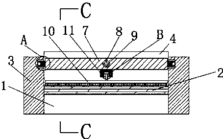
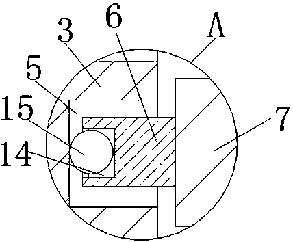
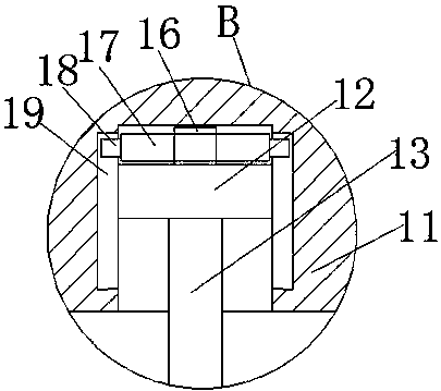

Image

  • Amorphous silicon annealing solar cell panel
  • Amorphous silicon annealing solar cell panel
  • Amorphous silicon annealing solar cell panel

Examples


Embodiment Construction

[0023] The following will clearly and completely describe the technical solutions in the embodiments of the present invention with reference to the accompanying drawings in the embodiments of the present invention. Obviously, the described embodiments are only some, not all, embodiments of the present invention.

[0024] In describing the present invention, it should be understood that the terms "upper", "lower", "front", "rear", "left", "right", "top", "bottom", "inner", " The orientation or positional relationship indicated by "outside", etc. is based on the orientation or positional relationship shown in the drawings, and is only for the convenience of describing the present invention and simplifying the description, rather than indicating or implying that the referred device or element must have a specific orientation, so as to Specific orientation configurations and operations, therefore, are not to be construed as limitations on the invention.

[0025] refer to Figure ...


PUM


Abstract

The invention discloses an amorphous silicon annealing solar cell panel. The amorphous silicon annealing solar cell panel comprises a substrate, wherein solar cell panels are installed on the substrate, and the solar cell panels are arranged on the substrate in a matrix mode, and are connected through connecting wires to form a circuit; the solar cell panels are made of an amorphous silicon film,wherein the amorphous silicon film is prepared by PECVD or APCVD deposition and has the thickness of 1-50mu; an annealing furnace is filled with N2, and high-temperature annealing is performed for 10hat 600 DEG C; a layer of polycrystalline silicon thin film is grown on the upper surface of a silicon wafer so as to complete the thermal annealing; sliding plates are fixedly connected to a pair ofvertical side walls of the substrate; a baffle is fixedly connected to one vertical side walls of the sliding plates; one side of the baffle is fixedly connected with the same ends of the two slidingplates; and sliding grooves are symmetrically formed in the opposite side walls of the two sliding plates. The amorphous silicon annealing solar cell panel is suitable for a conventional silk-screen printing all-aluminum back field battery and a back passivation point contact battery, and the service life of the solar cell panel is prolonged; and in addition, that dust and dirt on the solar cell panel can be effectively erased.

Description

technical field [0001] The invention relates to the technical field of solar cell equipment, in particular to an amorphous silicon annealed solar cell panel. Background technique [0002] Solar energy is renewable and clean energy. With the development of photovoltaic power generation technology, solar cell products are widely used in various types of products and building structures. In large-scale solar products and building structures, the solar cell area usually needs to be laid on a large area to meet the power consumption requirements. At the same time, in the solar building structure, the solar cell area is gradually departing from the conventional rectangular design, and is more inclined to design circular, fan-shaped, S-shaped and other special-shaped structures with arc boundaries to enhance the design aesthetics. All of these require splicing and laying a large number of solar cells, and at the same time require small seams and high matching between adjacent cel...

Claims


Application Information

Patent Timeline
Patent Type & Authority Applications(China)
IPC IPC(8): H01L31/0368H01L31/20H02S40/10
CPCH01L31/03682H01L31/202H02S40/10Y02E10/546Y02P70/50
Inventor 李雍李艳张仪
Owner GUANGZHOU TENGDAOLV POWER TECH DEV CO LTD
Learn More