Driving circuit, power electronic equipment and energy equipment

A driving circuit and driving resistor technology, applied in the direction of pulse duration/width modulation, pulse shaping, etc., can solve the problems of bridge arm crosstalk, misconduction of switching devices, and conventional device drivers, so as to reduce the problem of bridge arm crosstalk , The effect of preventing misconducting phenomenon

Pending Publication Date: 2019-03-01
GREE ELECTRIC APPLIANCES INC
View PDF0 Cites 0 Cited by
  • Summary
  • Abstract
  • Description
  • Claims
  • Application Information

AI Technical Summary

Problems solved by technology

[0004] However, in the driving process of silicon carbide power devices, there will also be problems that have not been encountered in conventional device drivers.
One of the more important problems is that in synchronous buck or synchronous boost circuits with the bridge arm structure as the basic topology, the turn-on or turn-off of one switching device will affect the other switching device, which is called the bridge arm crosstalk problem.
If the crosstalk is serious, when one switching device is turned on, the other switching device will be mis-conducted. At this time, the bus bar is short-circuited, and the triode may break down, which seriously endangers the safety of the equipment.

Method used


Image

  • Driving circuit, power electronic equipment and energy equipment
  • Driving circuit, power electronic equipment and energy equipment
  • Driving circuit, power electronic equipment and energy equipment

Examples


Embodiment Construction

[0026] Various exemplary embodiments of the present disclosure will now be described in detail with reference to the accompanying drawings. It should be noted that unless specifically stated otherwise, the relative arrangement of components and steps, numerical expressions and numerical values ​​set forth in these embodiments do not limit the scope of the present disclosure.

[0027] At the same time, it should be understood that, for ease of description, the sizes of the various parts shown in the drawings are not drawn according to actual proportional relationships.

[0028] The following description of at least one exemplary embodiment is actually only illustrative, and in no way serves as any limitation to the present disclosure and its application or use.

[0029] The technologies, methods, and equipment known to those of ordinary skill in the relevant fields may not be discussed in detail, but where appropriate, the technologies, methods, and equipment should be regarded as par...


PUM


Abstract

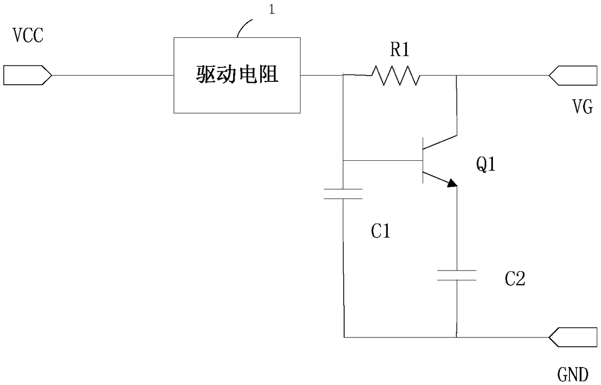
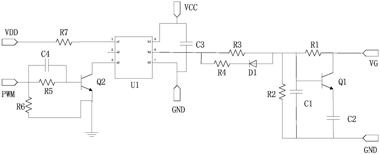
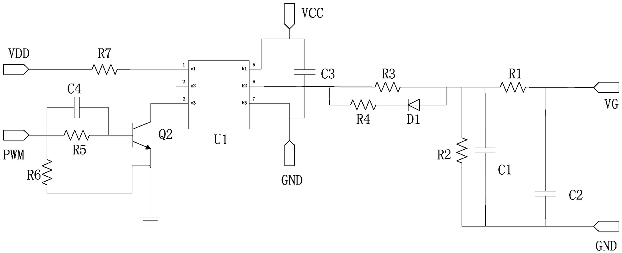
The invention provides a driving circuit, power electronic equipment and energy equipment, and relates to the technical field of power electronics. The driving circuit comprises a driving resistor, afirst resistor, a first capacitor, a second capacitor and a first switching part; the first end of the driving resistor is connected to the first power end; the first end of the first resistor is connected to the second end of the driving resistor; the second end is connected to the grid of a first bridge arm power switching device; the first end of the first capacitor is connected to the second end of the driving resistor; the second end is connected to the source of the first bridge arm power switching device; the first end of the second capacitor is connected to the second end of the firstcapacitor; the first end of the first switching device is connected to the first end of the first capacitor; the second end is connected to the second end of the first resistor; the third end is connected to the second end of the second capacitor, wherein the first switching device is on when a second bridge arm power switching device is on or off; and the first switching device is off when the second bridge arm power switching device normally works. By means of the driving circuit, the power electronic equipment and the energy equipment in the invention, the bridge arm crosstalk problem can be reduced.

Description

Technical field [0001] The present disclosure relates to the field of power electronics technology, and in particular to a drive circuit, power electronic equipment and energy equipment. Background technique [0002] At present, with the intelligent development of power electronic technology and the construction of the energy Internet, the application of power electronic equipment has gradually attracted people's attention. Among them, power switching devices are important components of power conversion circuits, and they are constantly developing. [0003] Among them, semiconductor power devices represented by silicon carbide and gallium nitride stand out, and they have excellent characteristics. In the field of high voltage and high power, silicon carbide has more advantages. Its band gap is 3 times that of silicon, its breakdown field strength is 10 times that of silicon, and its thermal conductivity is 2.5 times that of silicon, so its blocking voltage is high, The operating f...

Claims


Application Information

Patent Timeline
Patent Type & Authority Applications(China)
IPC IPC(8): H03K7/08H03K5/04
CPCH03K7/08H03K5/04
Inventor 蒋世用张祥张雪芬李萌陈宁宁
Owner GREE ELECTRIC APPLIANCES INC
Why Eureka
Try Eureka