
Coating processing apparatus and coating liquid collecting member

A technology for processing devices and coating liquids, which is applied in the direction of surface coating liquid devices, spraying devices, coatings, etc., which can solve problems such as poor productivity, lower exhaust pressure, and easy scattering of coating liquids, and achieve suppression Effect of accumulation, suppression of decrease in productivity

Active Publication Date: 2019-03-05
TOKYO ELECTRON LTD
View PDF8 Cites 2 Cited by
  • Summary
  • Abstract
  • Description
  • Claims
  • Application Information

AI Technical Summary

Problems solved by technology

In addition, there is a problem that if such a linear coating liquid is clogged in the exhaust passage, the exhaust pressure will decrease, so it is necessary to periodically perform maintenance to remove the linear coating liquid.
Therefore, it is difficult to stably supply the liquid toward the coating liquid collecting member during wafer processing.
Therefore, there is a problem that, in addition to the process of processing the wafer, it is necessary to perform a process of supplying the back side rinse liquid toward the coating liquid collecting member to clean the coating liquid collecting member, and the productivity deteriorates.
However, the linear coating liquid tends to scatter, and there is a possibility that the coating liquid captured by the exhaust gas cannot be sufficiently suppressed.
In addition, it is necessary to continuously supply the solvent during the resist coating process, so the amount of chemical solution used may increase

Method used


Image

  • Coating processing apparatus and coating liquid collecting member
  • Coating processing apparatus and coating liquid collecting member
  • Coating processing apparatus and coating liquid collecting member

Examples


Embodiment

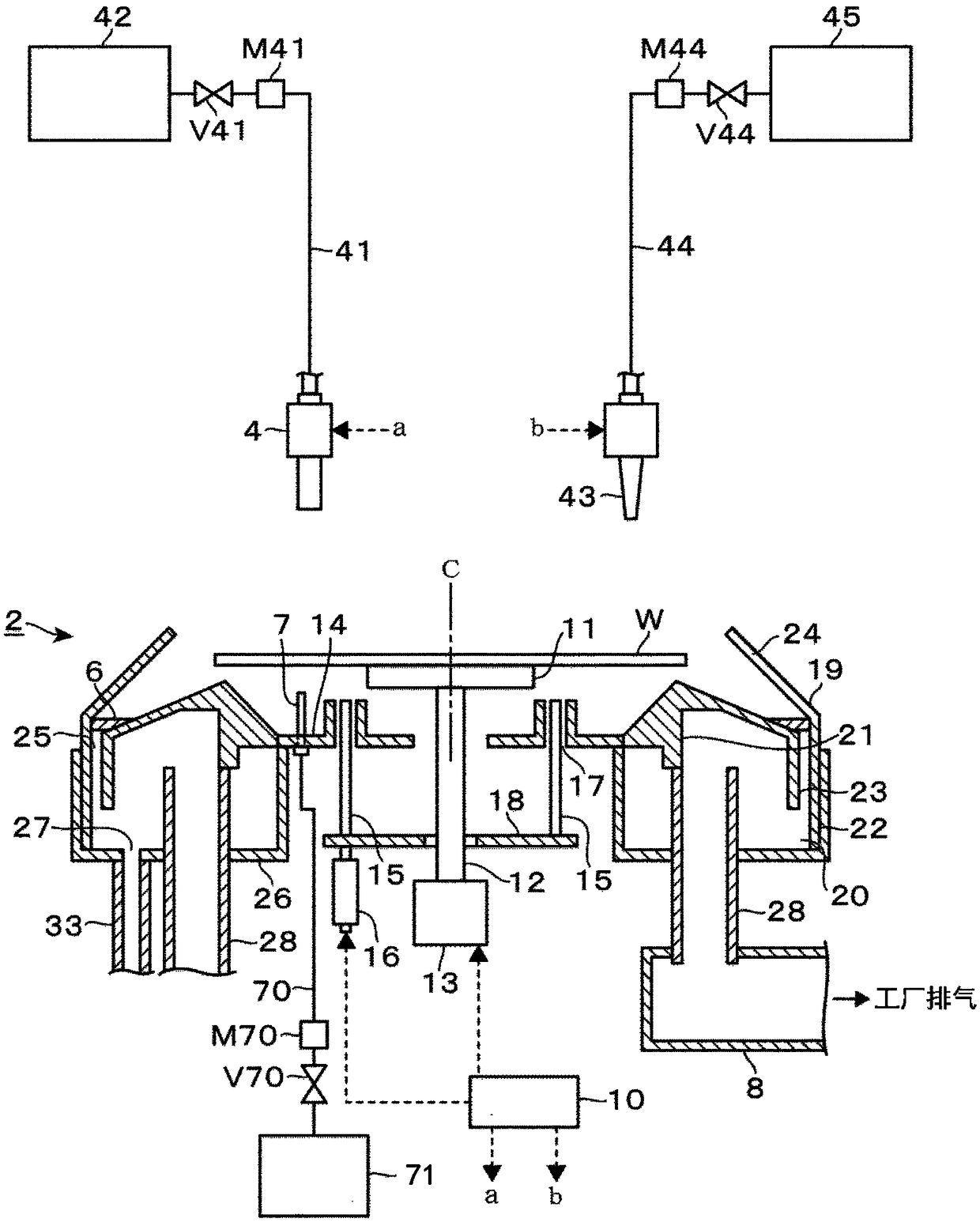
[0077] In order to verify the suppression of fluctuations in exhaust pressure due to the installation of coating liquid trapping members, use figure 1 In the resist coating apparatus shown, the set exhaust pressure of the cup body 2 set by the opening degree of the regulating valve provided to the exhaust duct 8 is set to 50 Pa, and the exhaust pressure shown in the embodiment is followed. In the method, 100 wafers W are coated with a resist solution, and the inside of the cup body 2 (closer to the coating liquid collection member 6) when 0, 25, 50, 75, and 100 wafers W are processed The exhaust pressure at the position on the downstream side) was measured. In addition, as a comparative example, processing was performed in the same manner as in the examples except that the coating liquid collecting member 6 was not provided.

[0078] Figure 13 This result is shown in a characteristic diagram in which the number of processed wafers W is shown on the horizontal axis and the ...


PUM


Abstract

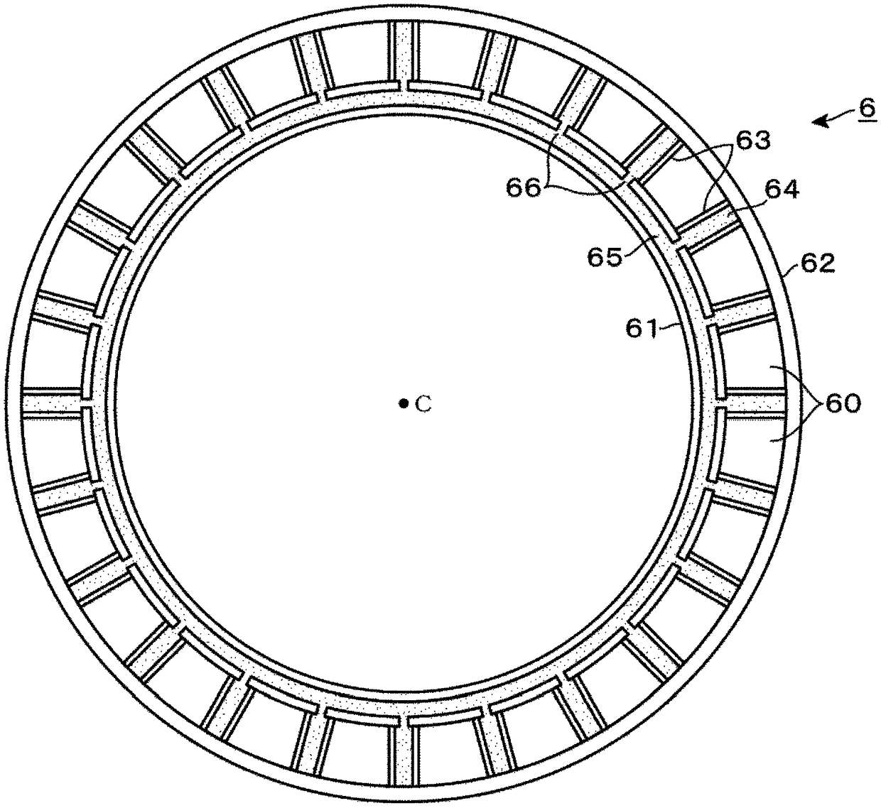
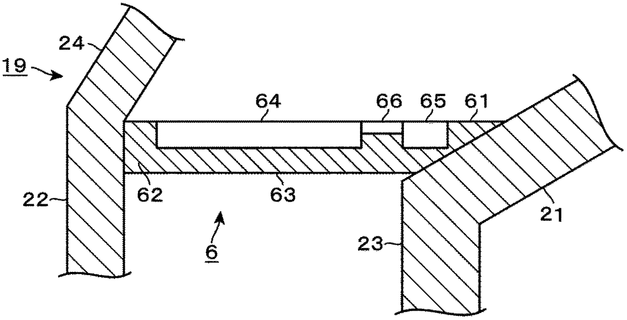
Some embodiments of the present disclosure provide a technique capable of collecting and removing a coating liquid scattering from a substrate when performing a coating process on the substrate onto which a coating liquid of high viscosity is supplied while rotating the substrate, and capable of suppressing degradation in throughput. In a resist coating apparatus that applies a resist liquid whilerotating a wafer, a coating liquid collecting member that traps a linear coating liquid generated by rotation of the wafer is provided in an exhaust path provided along a circumferential direction ofa cup body, and the coating liquid collecting member is provided with a solvent reservoir. When the wafer is subjected to the back side solvent supply treatment, the solvent that has been cleaved from the wafer falls to the coating liquid collecting member, and is stored in the solvent reservoir. In addition, when the solvent is deposited in the solvent reservoir, it is possible to dissolve and remove the linear coating liquid collected by the coating liquid collecting member during the resist coating process when the subsequent wafer is subjected to the resist coating treatment, thereby suppressing a decrease in productivity.

Description

technical field [0001] The present invention relates to a coating processing device and a coating liquid collecting member for collecting and removing coating liquid scattered from a substrate when the substrate is rotated to apply the coating liquid. Background technique [0002] There is known an apparatus for performing spin coating in which various coating liquids such as resist are supplied to the surface of a semiconductor wafer (hereinafter referred to as "wafer") in a photoresist process which is one of semiconductor manufacturing processes, The wafer is rotated to apply the coating liquid to the entire surface of the wafer. As such a coating processing device, a cup body is provided to surround the wafer held on the spin chuck to catch the coating liquid scattered from the wafer, and an annular cup body is provided along the circumferential direction of the cup body. The exhaust path exhausts the atmosphere around the wafer through the exhaust path. [0003] In re...

Claims


Application Information

Patent Timeline
IPC IPC(8): B05C5/02B05C11/10B05C13/02H01L21/027
CPCB05C5/02B05C11/10B05C11/1039B05C13/02H01L21/027H01L21/67017H01L21/67051H01L21/6715H01L21/68764H01L21/67023B05B14/30H01L21/67393B05C11/02H10K71/12
Inventor 上村良一
Owner TOKYO ELECTRON LTD
Learn More