Liquid pressure alternating pressure pump and pressure exchanging method thereof

A liquid pressure, liquid technology, applied in the direction of fluid pressure converter, mechanical equipment, etc., can solve the problems of crankshaft connecting rod structure volume and manufacturing cost, it is difficult to move the piston with large stroke, reduce the motor power output, and limit the unit recovery amount. , to achieve the effect of novel and flexible energy exchange method, increase the amount of liquid injected, and reduce energy loss

Inactive Publication Date: 2019-03-05
王建勋
View PDF10 Cites 0 Cited by
  • Summary
  • Abstract
  • Description
  • Claims
  • Application Information

AI Technical Summary

Problems solved by technology

[0002] In the production process of the chemical industry, there will be many pressurization and decompression situations. For example, in the high-pressure washing and absorption process, high-power plunger pumps and high-power multi-stage centrifugal pumps are mainly used for high-pressure liquid transportation, and the return flow from the washing and absorption devices The potential energy of the high-pressure liquid is simply decompressed. In order to reuse the potential energy of the high-pressure liquid returned by the washing device, the current method is to use a multi-stage centrifugal pump to equip a hydraulic turbine device or a turbine power generation device. The device is an energy-saving device that can partially recover the potential energy of liquid pressure and convert it into kinetic energy. The power jointly drives the multi-stage centrifugal pump to rotate and do work, thereby reducing the power output of the motor and achieving the purpose of saving energy. The advantage of this device is that the structure is simple, but the disadvantage is that the energy recovery efficiency is too low, and the recovery rate is the highest in practical applications. Only 30%, the energy saving effect is not obvious, the turbine power generation device is more complicated than the water conservancy turbine device and the energy recovery rate is low, and the general application is less
In order to overcome the above shortcomings, the inventor previously disclosed a "pressure exchange pump" with patent publication number CN203098431U and a "pressure exchange method for pressure exchange pump" with patent publication number CN104019065A, which can realize direct conversion of high-pressure liquid energy and It can be recycled efficiently, but this technical solution needs to use a low-power motor as supporting power to drive the crankshaft connecting rod, and then connect the crankshaft connecting rod with the piston rod to drive the piston movement in the exchange pump, so the cost input is relatively high ;The crankshaft and connecting rod structure is difficult to realize the large stroke movement of the piston from the volume to the manufacturing cost, which limits the unit recovery of high-pressure liquid energy; if the potential energy recovery is not the same liquid, or the liquid pressure is different, the above technology The program is also incapable of

Method used


Image

  • Liquid pressure alternating pressure pump and pressure exchanging method thereof
  • Liquid pressure alternating pressure pump and pressure exchanging method thereof
  • Liquid pressure alternating pressure pump and pressure exchanging method thereof

Examples


Embodiment 1

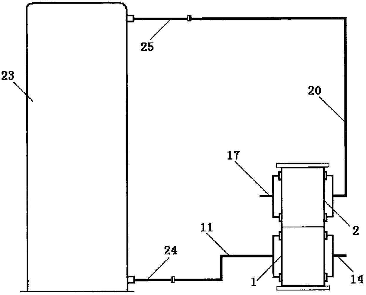
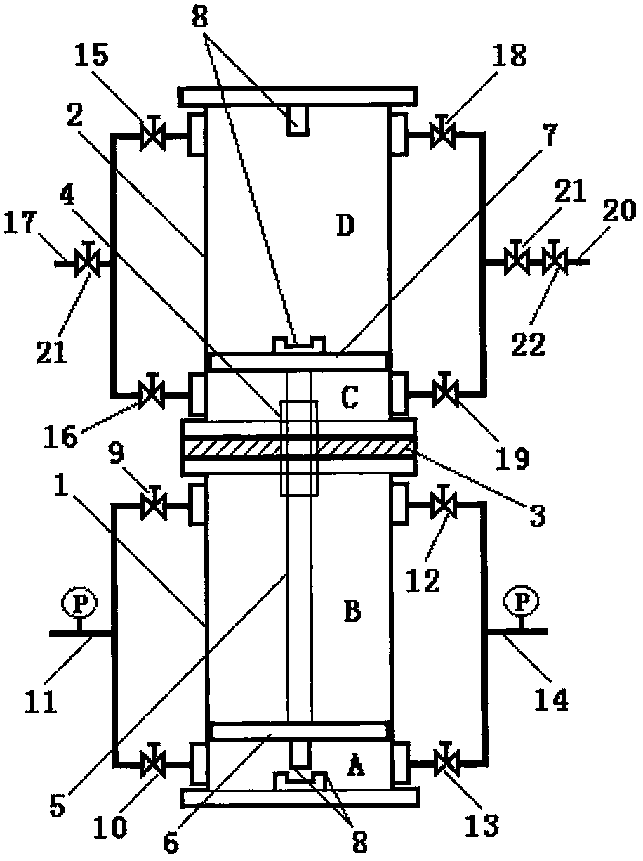
[0027] Embodiment one: if figure 1 , 2 As shown, taking the pipeline connecting the self-operated liquid pressure alternating pressure pump to the high-pressure washing tower 23 as an example, the power cylinder 1 is connected to the liquid outlet pipe 24 of the high-pressure washing tower 23 through the power liquid inlet main pipe 11, and the power liquid discharge main pipe 14 goes to To the next process; the pump liquid cylinder body 2 is connected to the upper liquid pipe 25 of the high-pressure washing tower 23 through the pump liquid discharge main pipe 20, and the pump liquid inlet main pipe 17 is connected to the solvent storage tank.

[0028] The pressure exchange method of the self-operated liquid pressure alternating pressure pump comprises the following steps:

[0029] a. When the power piston 6 and the pump liquid piston 7 are at the bottom of the stroke, the power lower liquid inlet valve 10 is opened, and at the same time the power upper liquid discharge valve...

Embodiment 2

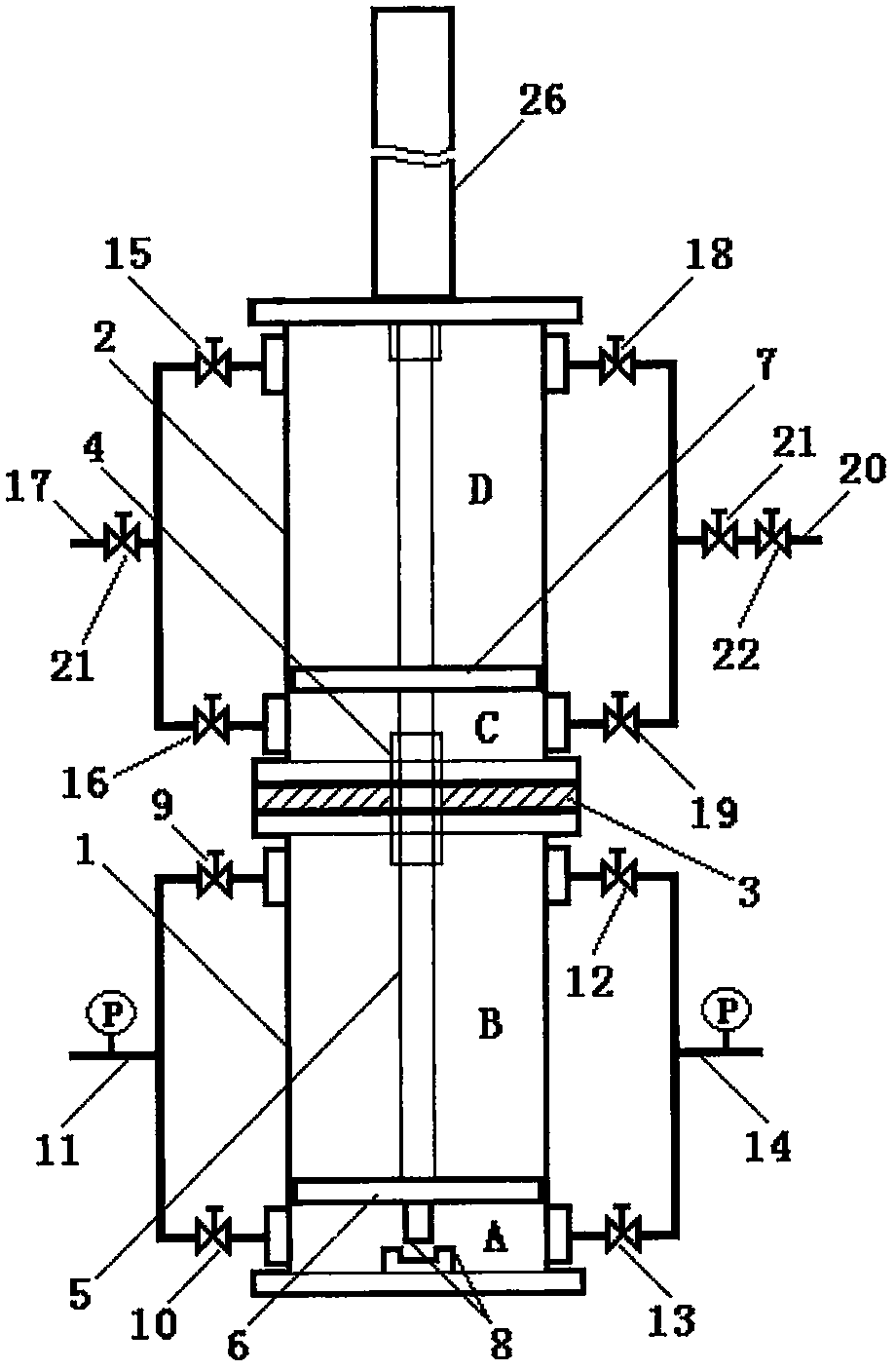
[0033] Embodiment two: if image 3 As shown, the power-assisted liquid pressure alternating pressure pump can be applied under special conditions, and its working principle is basically the same as that of the self-powered liquid pressure alternating pressure pump. There is a power-assisted hydraulic cylinder 26, and the upper end of the piston rod 5 is extended, which is also the piston rod of the power-assisted hydraulic cylinder. The power-assisted hydraulic cylinder 26 can assist the automatic operation of the two pistons under the timing control of the system, increasing the volume of pumping fluid and improving energy efficiency. Recovery rate, easy to control the operation of the pump.

[0034] The invention can work with a single pump or in groups. When the liquid exchange volume is large, the groups operate in a time-series network, and are especially suitable for application in modern large-scale industrial production processes.

[0035] Considering the economy, thi...


PUM


Abstract

The invention discloses a liquid pressure alternating pressure pump which comprises a power cylinder block, a liquid pumping cylinder block, a partition plate, a guide sleeve sealing assembly, a piston rod, a power piston, a liquid pumping piston, a buffer device, a power upper liquid inlet valve, a power lower liquid inlet valve, a power liquid inlet manifold, a power upper drain valve, a power lower drain valve, a power drain manifold, a fluid pumping upper liquid inlet valve, a fluid pumping lower liquid inlet valve, a liquid pumping upper drain valve, a liquid pumping lower drain valve, aliquid pumping drain manifold, a check valve and a cut-off valve; and the power cylinder block and the liquid pumping cylinder block are integrally connected up and down into a whole, the partition plate is arranged between the two cylinder blocks, a guide sleeve sealing assembly is arranged in the center of the partition plate, the lower end of the piston rod is connected with the power piston, the upper end of the piston rod is connected with the liquid pumping piston, the liquid inlet valves and the drain valves are arranged at the upper and lower ends of the two cylinder blocks, and the buffer devices are arranged in the cylinder blocks. The liquid pressure alternating pressure pump is characterized in that the energy exchange method is novel and flexible, and the energy recovery efficiency is high; the application range is wide; and the structure is simple and practical, the power consumption is saved, and the production cost is saved.

Description

technical field [0001] The invention relates to a pressure exchange and variable pressure device of liquid flow, in particular to a liquid pressure alternating pressure pump, and also relates to a pressure exchange method of the liquid pressure alternating pressure pump. Background technique [0002] In the production process of the chemical industry, there will be many pressurization and decompression situations. For example, in the high-pressure washing and absorption process, high-power plunger pumps and high-power multi-stage centrifugal pumps are mainly used for high-pressure liquid transportation, and the return flow from the washing and absorption devices The potential energy of the high-pressure liquid is simply decompressed. In order to reuse the potential energy of the high-pressure liquid returned by the washing device, the current method is to use a multi-stage centrifugal pump to equip a hydraulic turbine device or a turbine power generation device. The device i...

Claims


Application Information

Patent Timeline
Patent Type & Authority Applications(China)
IPC IPC(8): F15B3/00
CPCF15B3/00
Inventor 王建勋
Owner 王建勋
Why Eureka
Try Eureka