Automatic cutting device for composite material standard plates for high-speed rail

A technology for composite materials and cutting devices, applied in feeding devices, cutters for milling machines, large fixed members, etc., can solve problems such as low precision, cost sensitivity, and high maintenance costs, and achieve improved work efficiency, stable quality, and simple structure Effect

Pending Publication Date: 2019-03-08
ADESSO ADVANCED MATERIALS WUXI CO LTD
View PDF1 Cites 0 Cited by
  • Summary
  • Abstract
  • Description
  • Claims
  • Application Information

AI Technical Summary

Problems solved by technology

[0002] With the development of automatic mass production technology of composite materials, the manufacturing cost of composite materials has been greatly reduced. Therefore, the application of composite materials on standard plates in the high-speed rail industry has also made great progress. When using standard plates of composite materials, they need to be pre-cut into required When the shape, especially the standard plate of 0.4-5mm needs to be cut quickly, the traditional cutting process has a low degree of automation and often uses manual cutting, which has low precision and unstable quality. The quality fluctuation of different batches or even different parts of the same batch is relatively large. Large, but it will also affect the use of products. The high-speed rail industry has large batches, high quality requirements, and is cost-sensitive. Manual cutting will virtually increase the cost of personnel. Automatic cutting devices that appear on the market are often expensive, and the purchase price is high. , the maintenance cost is high, so there is an urgent need for an automatic cutting device with high production efficiency, low cost and stable quality
[0003] Chinese patent application CN107160475A discloses a plate cutting machine, including a base, a first telescopic mechanism, a second telescopic mechanism and a bracket are arranged on the top surface of the base, and the first telescopic mechanism is arranged on the top surface of the base One end of the first telescopic mechanism is provided with a baffle, the second telescopic mechanism is arranged on one side of the top surface of the base, the end of the second telescopic mechanism is provided with a push plate, and the bracket is fixed on the other side of the top surface of the base. At one end, the bracket is provided with a cross bar, and the cross bar is provided with a first lifting mechanism and a second lifting mechanism. The ends of the first lifting mechanism and the second lifting mechanism face the top surface of the base, and the ends of the first lifting mechanism are fixed. There is a pressure block, the end of the second lifting mechanism is fixed with a cutter installation structure, the cutter installation structure is located between the baffle and the pressure block, and the bottom of the cutter installation structure is installed with horizontal and vertical cutters. The advantage of this device is that : Realized horizontal and vertical cutting, but the device has a high manufacturing cost and for different sheet widths, different height adjustments during cutting have not been mentioned, so it can be further improved

Method used


Image

  • Automatic cutting device for composite material standard plates for high-speed rail
  • Automatic cutting device for composite material standard plates for high-speed rail
  • Automatic cutting device for composite material standard plates for high-speed rail

Examples


Embodiment 1

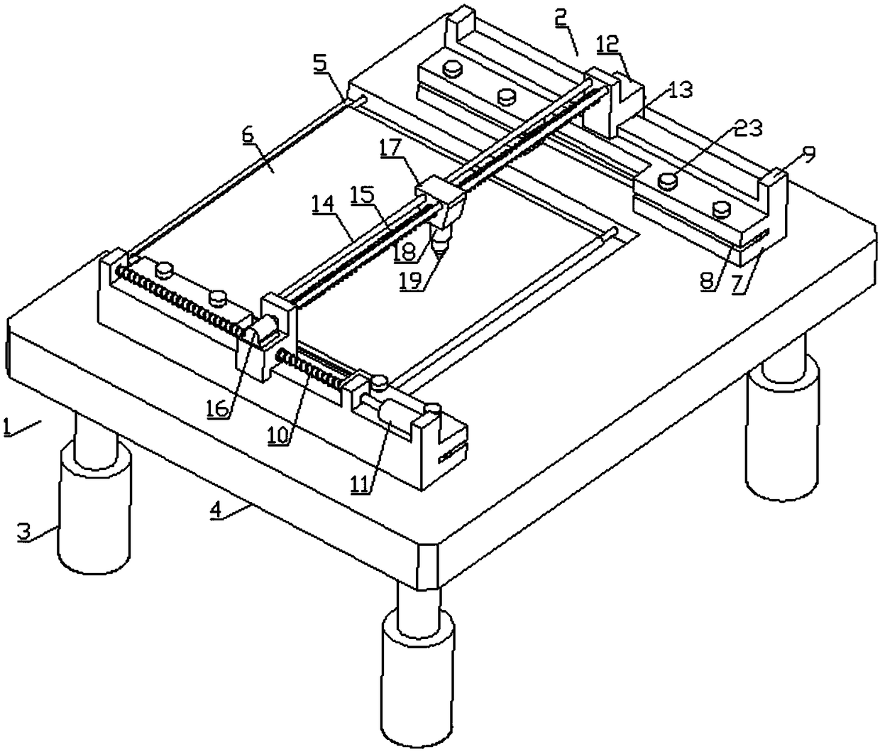
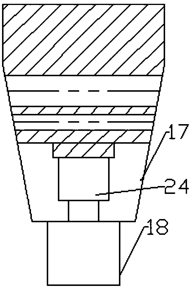
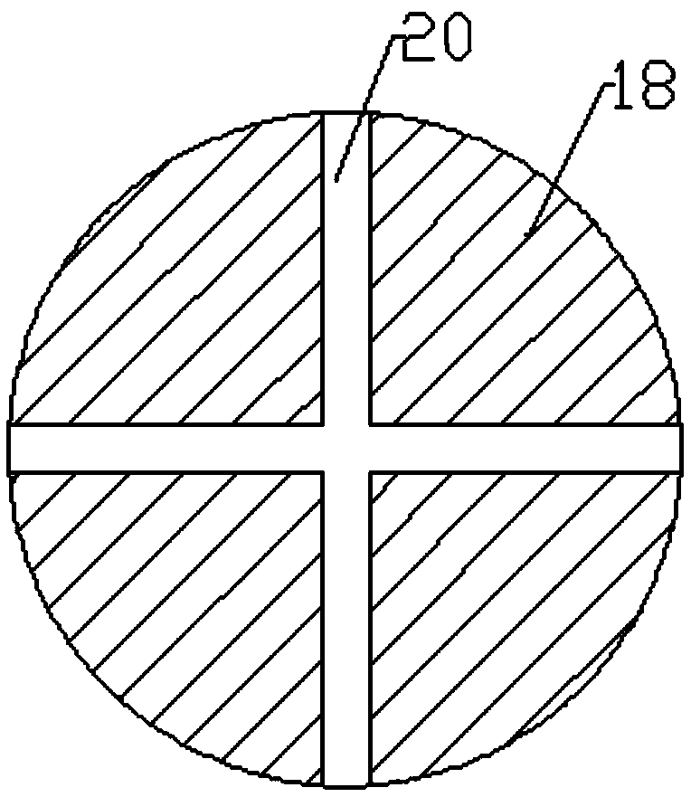
[0019] Such as Figure 1 to Figure 4 As shown, an automatic cutting device for composite material standard plates for high-speed rail includes a cutting frame 1 and a cutting mechanism 2. The cutting frame 1 includes four hydraulic rods 3 with the same structure, and the upper parts of the hydraulic rods 3 are fixedly connected. A work surface 4, the surface of the work surface 4 is provided with a blanking trough 5, a conveyor belt 6 is installed in the blank trough 5, and two bases 7 are fixedly connected to the work surface 4, and the middle part of the base 7 is There is a relief groove and a clamping groove 8 on its side, the edge position of the base 7 is fixedly connected to the slide rails 9, and the side walls of one of the slide rails 9 are rotated to connect the threaded rod-10, the threaded rod-10 One end is connected to the output shaft of the motor one 11, and the motor one 11 is fixedly connected to a side wall of the slide rail 9, and the cutting mechanism 2 is...

Embodiment 2

[0023] Such as Figure 1 to Figure 4 As shown, an automatic cutting device for composite material standard plates for high-speed rail includes a cutting frame 1 and a cutting mechanism 2. The cutting frame 1 includes four hydraulic rods 3 with the same structure, and the upper parts of the hydraulic rods 3 are fixedly connected. A work surface 4, the surface of the work surface 4 is provided with a blanking trough 5, a conveyor belt 6 is installed in the blank trough 5, and two bases 7 are fixedly connected to the work surface 4, and the middle part of the base 7 is There is a relief groove and a clamping groove 8 on its side, the edge position of the base 7 is fixedly connected to the slide rails 9, and the side walls of one of the slide rails 9 are rotated to connect the threaded rod-10, the threaded rod-10 One end is connected to the output shaft of the motor one 11, and the motor one 11 is fixedly connected to a side wall of the slide rail 9, and the cutting mechanism 2 is...


PUM

PropertyMeasurementUnit
Densityaaaaaaaaaa
Tensile modulusaaaaaaaaaa

Abstract

The invention discloses an automatic cutting device for composite material standard plates for a high-speed rail and relates to the technical field of plate cutting. The automatic cutting device comprises a cutting frame and a cutting mechanism. The cutting frame comprises four hydraulic rods of the same structure. The automatic cutting device is simple in structure and convenient and fast to operate; the automatic cutting function can be realized by arranging the cutting mechanism, and the working efficiency is improved; meanwhile, the height of the top of a worktable can be adjusted by starting the hydraulic rods according to the height of a worker or the height matching requirements of other equipment; and the automatic cutting device is high in practicability, convenient to maintain, low in cost and stable in quality.

Description

technical field [0001] The invention relates to the technical field of plate cutting, in particular to an automatic cutting device for a composite material standard plate for high-speed rail. Background technique [0002] With the development of automatic mass production technology of composite materials, the manufacturing cost of composite materials has been greatly reduced. Therefore, the application of composite materials on standard plates in the high-speed rail industry has also made great progress. When using standard plates of composite materials, they need to be pre-cut into required When the shape, especially the standard plate of 0.4-5mm needs to be cut quickly, the traditional cutting process has a low degree of automation and often uses manual cutting, which has low precision and unstable quality. The quality fluctuation of different batches or even different parts of the same batch is relatively large. Large, but it will also affect the use of products. The high...

Claims


Application Information

Patent Timeline
IPC IPC(8): B23C3/00B23Q1/25B23Q5/40
CPCB23C3/00B23Q1/25B23Q5/402B23C2226/27
Inventor 崔国新南江琨白灵刘洋
Owner ADESSO ADVANCED MATERIALS WUXI CO LTD
Why Eureka
Try Eureka