Semi-automatic high-precision cap screwing machine based on ultrasonic friction reducing effect
An ultrasonic anti-friction, semi-automatic technology, applied in applications, screw caps, bottle/container caps, etc., can solve the problems of increased production costs, low efficiency of capping machines, complicated operations, etc., to achieve stable operation and solve capping problems. The effect of low efficiency and broad market prospects
- Summary
- Abstract
- Description
- Claims
- Application Information
AI Technical Summary
Problems solved by technology
Method used
Image

Examples
specific Embodiment approach 1
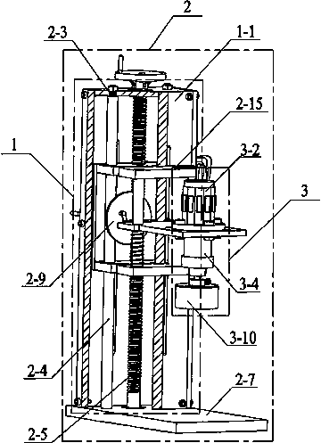
[0036] Specific implementation mode one: combine Figure 1~Figure 11 Describe this embodiment. This embodiment provides a specific implementation of a semi-automatic high-precision capping machine based on the ultrasonic anti-friction effect. The specific implementation of the semi-automatic high-precision capping machine based on the ultrasonic anti-friction effect The way is expressed as follows:
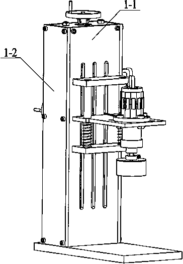
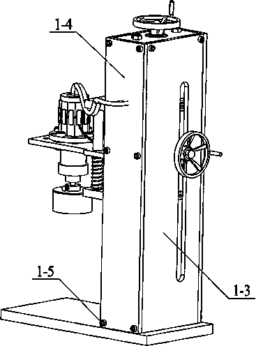
[0037] Such as figure 1 As shown, the semi-automatic high-precision capping machine based on the ultrasonic anti-friction effect includes a device housing 1, a lifting positioning system 2 and a capping device 3; wherein, the lifting positioning system 2 constitutes the main body support of the capping machine The device shell 1 is installed on the peripheral frame of the lifting positioning system 2, which is used for semi-enclosed packaging of the lifting positioning system 2, and the capping device 3 is fixed on the lifting positioning system 2.
[0038] Such as Figure 2~3 ...
specific Embodiment approach 2
[0041] Specific implementation mode two: combination Figure 8 , 9 , 12~14 illustrate this implementation mode, this implementation mode provides a method based on d 15 The specific implementation of the capping device 3 of the semi-automatic high-precision capping machine with mode ultrasonic anti-friction effect. The difference between this embodiment and the first embodiment is that the capping device 3 includes a piezoelectric shearing plate 3-11 , lower base 3-12, upper base 3-13, mounting screw 3-14, air guiding mechanism 3-3, threaded drive shaft 3-4, rubber sealing ring 3-5, piston assembly 3-6, cover 3-7. Outreach mechanism 3-8, locking screw 3-9 and capping head 3-10; wherein, the piezoelectric shear piece 3-11 can be a product of PI or NEC, and the gas guiding mechanism The upper end of 3-3 is provided with an external thread 3-3-1 of the air guide mechanism, and the threaded drive shaft 3-4 includes a drive shaft internal thread hole 3-4-1, a drive shaft external...
specific Embodiment approach 3
[0042] Specific implementation mode three: combination Figure 8 , 9 , 15~17 illustrate this implementation mode, this implementation mode provides a method based on d 33The specific implementation of the capping device 3 of the semi-automatic high-precision capping machine with mode ultrasonic friction reduction effect. The difference between this embodiment and the first embodiment is that the capping device 3 includes an ultrasonic friction reduction component 3-15, Upper cover 3-16, air guide mechanism 3-3, threaded drive shaft 3-4, rubber sealing ring 3-5, piston assembly 3-6, cover 3-7, external connection mechanism 3-8, locking screw 3-9 and capping head 3-10; wherein, the upper end of the air guiding mechanism 3-3 is provided with an external thread 3-3-1 of the air guiding mechanism, and the threaded drive shaft 3-4 includes a drive shaft internally threaded hole 3 -4-1. Drive shaft external thread 3-4-2 and sealing ring groove I3-4-3, the ultrasonic antifriction co...
PUM
 Abstract
Description
Claims
Application Information
 - Generate Ideas
- Intellectual Property
- Life Sciences
- Materials
- Tech Scout
- Unparalleled Data Quality
- Higher Quality Content
- 60% Fewer Hallucinations
Browse by: Latest US Patents, China's latest patents, Technical Efficacy Thesaurus, Application Domain, Technology Topic, Popular Technical Reports.
© 2025 PatSnap. All rights reserved.Legal|Privacy policy|Modern Slavery Act Transparency Statement|Sitemap|About US| Contact US: help@patsnap.com