Stainless steel base water electrolysis catalytic electrode and manufacturing method thereof

A catalytic electrode, stainless steel technology, applied in the direction of electrodes, electrolysis process, electrolysis components, etc., can solve the problems of not being able to use as a catalyst for total water splitting, poor performance of electrocatalytic hydrogen evolution, etc., and achieve excellent stability, optimized performance, and strong nanostructure Effect

Inactive Publication Date: 2019-03-08
TSINGHUA UNIV
View PDF4 Cites 7 Cited by
  • Summary
  • Abstract
  • Description
  • Claims
  • Application Information

AI Technical Summary

Problems solved by technology

The surface of the stainless steel treated in this way is enriched with Fe and Ni elements, showing good electrocatalytic oxygen evolution performance, but the electrocatalytic hydrogen evolution performance is not good, so it cannot be used as an efficient total water splitting catalyst

Method used


Image

  • Stainless steel base water electrolysis catalytic electrode and manufacturing method thereof
  • Stainless steel base water electrolysis catalytic electrode and manufacturing method thereof
  • Stainless steel base water electrolysis catalytic electrode and manufacturing method thereof

Examples


preparation example Construction

[0031] Concrete preparation method of the present invention comprises the steps:

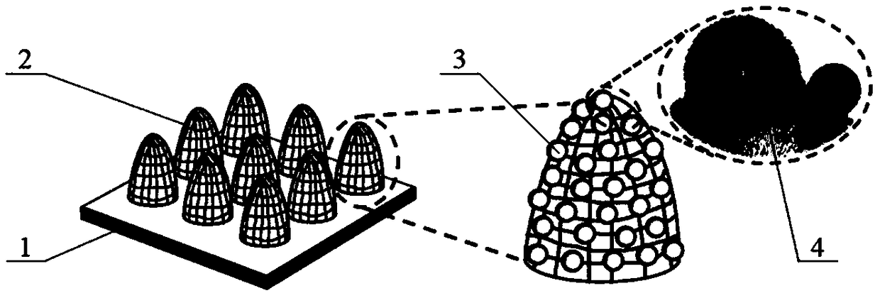
[0032] 1) Using a high-energy-density pulsed laser to ablate the surface of the stainless steel substrate, and scanning according to a vertical intersection path to form a three-dimensional micro-protrusion array, the high-energy-density pulsed laser can be a femtosecond, picosecond or nanosecond laser; The ablation path It is a vertical cross scanning method, the scanning distance is 20-200μm, and the scanning speed is 100-2000mm / s.

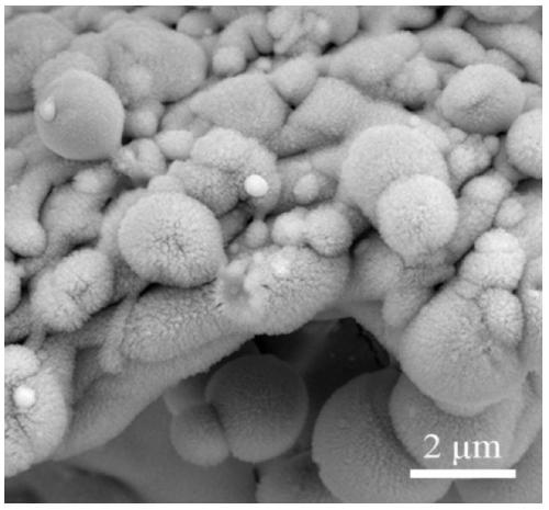
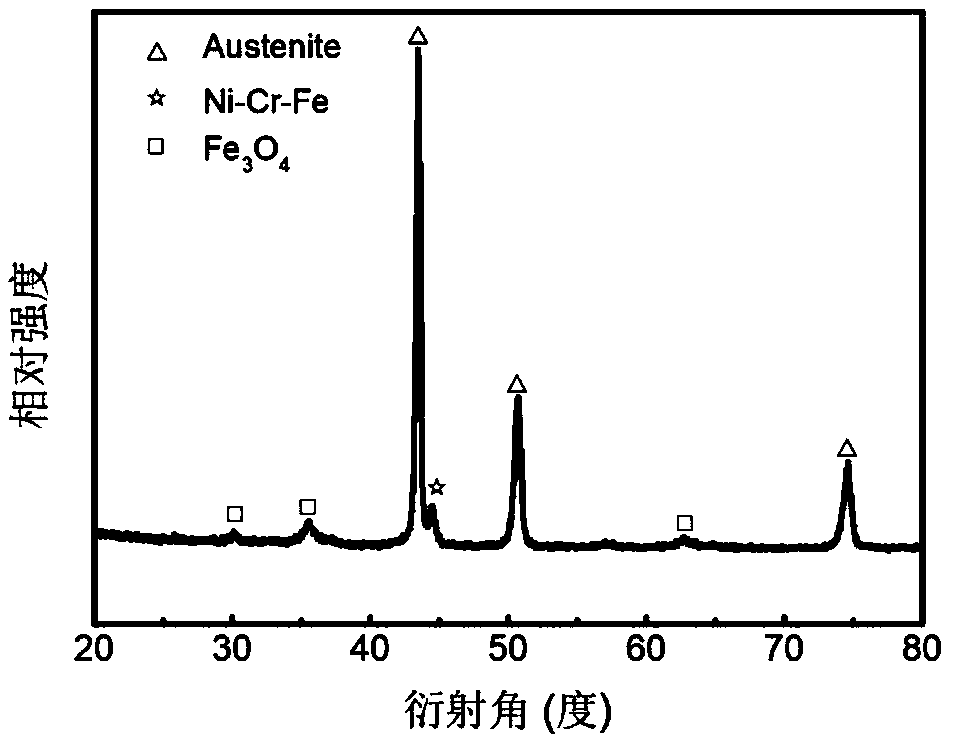
[0033] 2) Using nanosecond pulsed laser to irradiate the surface of the stainless steel substrate with convex arrays in the atmospheric environment, and also scan according to the vertical cross path, The scanning distance is 10-100μm, and the scanning speed is 20-1000mm / s; The microspheres and the oxide nano-velvet structure covering the surface of the raised array are ablated to form a three-dimensional self-supporting micro-nano composite multi-level struct...

Embodiment 1

[0036] Embodiment 1: In the two-step ablation process, the first step uses a femtosecond laser to ablate, and the second step uses a nanosecond laser to prepare an electrolytic water catalytic electrode, including the following steps:

[0037] 1) Cut the stainless steel sheet to a size of 10×20×0.3mm 3 The small piece of substrate, tear off the protective film;

[0038] 2) The femtosecond laser is used to perform the first ablation on the surface of the stainless steel substrate, wherein the laser wavelength is 1030nm, the pulse width is 800fs, the pulse repetition frequency is 200kHz, the average power is 20W, the scanning path is vertical cross lines, and the scanning distance is 100μm , the scanning speed is 2000mm / s;

[0039] 3) The second ablation is performed with a nano-laser, wherein the laser wavelength is 1030nm, the pulse width is 10ns, the pulse repetition frequency is 60kHz, the average power is 20W, the scanning path is vertical crossing lines, the scanning dist...

Embodiment 2

[0041] Embodiment 2: Two-step ablation adopts nanosecond laser to prepare electrolytic water catalytic electrode, including the following steps:

[0042] 1) Cut the stainless steel sheet to a size of 10×20×0.3mm 3 A small piece of substrate, tear off the protective film.

[0043] 2) Use a nanosecond laser to perform the first ablation on the surface of the stainless steel substrate, where the laser wavelength is 1030nm, the pulse width is 500ns, the pulse repetition frequency is 90kHz, the average power is 36W, the scanning path is vertical cross lines, and the scanning distance is 70μm , the scanning speed is 1000mm / s.

[0044] 3) The second ablation is performed with a nano-laser, wherein the laser wavelength is 1030nm, the pulse width is 800ns, the pulse repetition frequency is 100kHz, the average power is 50W, the scanning path is vertical cross lines, the scanning distance is 30μm, and the scanning speed is 1000mm / s. Then the sample was ultrasonically cleaned in anhyd...


PUM

PropertyMeasurementUnit
heightaaaaaaaaaa
diameteraaaaaaaaaa
diameteraaaaaaaaaa

Abstract

The invention belongs to the technical field of manufacturing of electro-catalysis materials and provides a stainless steel base water electrolysis catalytic electrode and a manufacturing method of the stainless steel base water electrolysis catalytic electrode. According to the stainless steel base water electrolysis catalytic electrode, a three-dimensional micron protrusion array is distributedon a stainless steel matrix. Micro-spheres of different sizes are distributed on the surface of the protrusion array at random. The surfaces of the micro-spheres are covered with oxide nanometer flossy structures formed by disordered stacking of nanometer particles. The manufacturing method of the stainless steel base water electrolysis catalytic electrode comprises the steps that firstly, high-energy-density pulse laser is utilized to conduct ablation on the surface of the stainless steel matrix so that the micron protrusion array can be formed; then, nanosecond pulse laser is utilized to conduct ablation on the surface of the protrusion array so that the micro-spheres and the nanometer flossy structures can be formed, and then the self-supporting electrolytic electrode without the need for an adhesion agent is obtained. The stainless steel base water electrolysis catalytic electrode has excellent water electrolysis hydrogen and oxygen evolution performance, overall water splitting performance and high stability; the manufacturing method is simple and controllable, large-area manufacturing can be achieved, raw materials are low in cost and easy to obtain, and the stainless steel base water electrolysis catalytic electrode can be used for wide application fields such as the field of hydrogen for fuel cell cars, the field of underwater equipment oxygen generation, the field of medical oxygen generation, the field of hydrogen water cups, the field of highland oxygen generation and the field of portable hydrogen and oxygen generating devices.

Description

technical field [0001] The invention specifically relates to a stainless steel-based electrolytic water catalytic electrode and a laser preparation method thereof, belonging to the technical field of electrocatalytic material preparation. Background technique [0002] Fossil fuels and their derivatives have penetrated into every aspect of human daily life. The normal operation of modern society is inseparable from the dependence on traditional fossil fuels. The rapid economic development has intensified the consumption of fossil fuels. Therefore, human beings are facing increasingly increasing energy pressure. On the one hand, fossil fuels, such as coal, oil, and natural gas, have limited and non-renewable reserves in the earth's crust, and will eventually be exploited and exhausted. On the other hand, the mining, refining and burning of fossil fuels will have adverse effects on the human living environment. The emissions of nitrogen oxides and sulfides may form acid rain, ...

Claims


Application Information

Patent Timeline
Patent Type & Authority Applications(China)
IPC IPC(8): C25B1/04C25B11/06
CPCC25B1/04C25B11/04Y02E60/36
Inventor 钟敏霖张红军蔡明勇
Owner TSINGHUA UNIV
Why Eureka
Try Eureka