Heat-setting machine
A technology of heat setting machine and machine body, which is applied in the direction of heating/cooling fabrics, textiles and papermaking, fabric surface trimming, etc. It can solve the problems of uneven distribution of hot air, poor drying effect of materials, and long time consumption, so as to prevent heat loss, The effect of short time consumption and prevention of thermal shock
- Summary
- Abstract
- Description
- Claims
- Application Information
AI Technical Summary
Problems solved by technology
Method used
Image
Examples
Embodiment 1
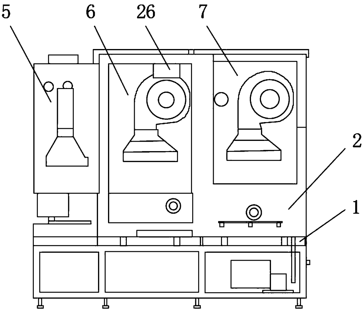
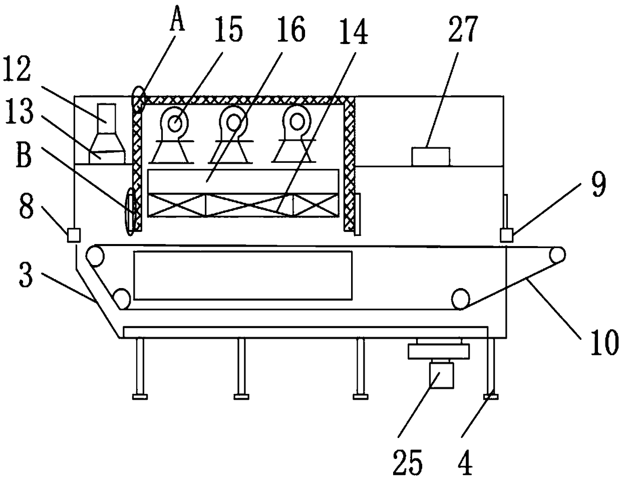
[0025] refer to Figure 1-4 , a heat setting machine, comprising a body 1, an oven 2 is fixedly installed in the body 1, and the oven 2 includes: a box body 3, a support frame 4, a preheating chamber 5, a heating chamber 6, a cooling chamber 7, an inlet A feed port 8, a discharge port 9 and a conveying device 10, the box body 3 is fixedly installed on the support frame 4, one side of the box body 3 is provided with a feed port 8, and the other side of the box body 3 A discharge port 9 is provided, and a preheating chamber 5 is provided on one side of the feed port 8 near the discharge port 9, and a heating chamber 6 is provided on one side of the preheating chamber 5, and a heating chamber 6 is provided on one side of the heating chamber 6 A cooling chamber 7 is provided on the side, and an adjusting device 11 is provided on both sides of the heating chamber 6. The adjusting device 11 is movable. When the material enters the heating chamber 6 for high-temperature drying treatm...
Embodiment 2
[0028] The adjusting device 11 includes: an adjusting rod 17, a worm 18, a screw 19 and an adjusting plate 20. The upper end of the adjusting rod 17 is fixedly connected with a worm 18, and one side of the upper end of the worm 18 is connected with a screw 19 through a gear. , the upper end of the screw mandrel 19 is fixedly connected with an adjustment plate 20, the outside of the adjustment device 11 is provided with a knob 28, the knob 28 is fixedly connected with the worm screw 18, and the knob 28 is rotated by hand, and the knob 28 drives the worm screw 18 to rotate, The worm 18 and the screw 19 are connected by a gear, and the worm 18 drives the gear to rotate, and the rotation of the gear makes the screw 19 rise or fall, and the adjusting plate 20 on the screw 19 also rises or falls, and when the material enters the heating chamber 6, the adjustment The downward adjustment of the plate 20 makes the heating chamber 6 airtight, prevents heat loss, facilitates the drying of...
Embodiment 3
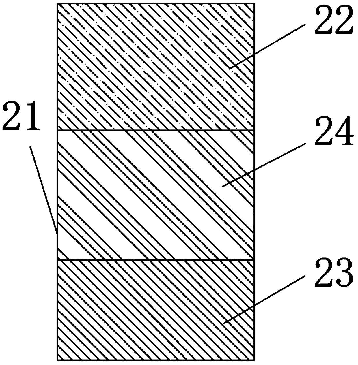
[0030] The inner wall of the heating chamber 6 is provided with a thermal insulation layer 21, and the thermal insulation layer 21 includes: an aluminum silicate fiber cotton layer 22, an anti-crack layer 23 and a bonding layer 24, and the top of the bonding layer 24 is fixedly connected with The aluminum silicate fiber cotton layer 22, the anti-crack layer 23 is fixedly connected to the bottom of the bonding layer 24, the aluminum silicate fiber cotton layer 22 is made of aluminum silicate fiber, which is a new type of light-weight thermal insulation material. It has the advantages of light bulk density, high temperature resistance, good thermal stability, low thermal conductivity, and good heat insulation performance. The crack-resistant layer 23 can prevent the thermal insulation layer 21 from cracking due to high temperature. The bonding layer 24 connects the crack-resistant layer 23 with silicon An acid aluminum fiber cotton layer 22 is bonded to prevent the loss of heat; ...
PUM
 Abstract
Description
Claims
Application Information
 - R&D Engineer
- R&D Manager
- IP Professional
- Industry Leading Data Capabilities
- Powerful AI technology
- Patent DNA Extraction
Browse by: Latest US Patents, China's latest patents, Technical Efficacy Thesaurus, Application Domain, Technology Topic, Popular Technical Reports.
© 2024 PatSnap. All rights reserved.Legal|Privacy policy|Modern Slavery Act Transparency Statement|Sitemap|About US| Contact US: help@patsnap.com


