
Furnace tube

A furnace tube and connecting tube technology is applied to the furnace tube. field, it can solve the problems of inconvenient workers, easy to burst, inconvenient disassembly, etc., and achieve the effect of enhancing pressure bearing capacity, prolonging service life and improving efficiency

Active Publication Date: 2019-03-08
阜阳汇中芯自动化技术有限公司
View PDF8 Cites 2 Cited by
  • Summary
  • Abstract
  • Description
  • Claims
  • Application Information

AI Technical Summary

Problems solved by technology

[0004] However, after analysis, it is found that an existing industrial furnace that is convenient for replacing the furnace tube has the following deficiencies; one: it cannot be easily disassembled, which brings great inconvenience to the workers; second: the industrial furnace tube cannot be easily removed Fix it to the surface of the industrial furnace; third: the industrial furnace tube cannot withstand greater pressure and is easy to burst

Method used


Image

  • Furnace tube
  • Furnace tube
  • Furnace tube

Examples


Embodiment Construction

[0019] The following will be combined with Figure 1-Figure 4 The present invention is described in detail, and the technical solutions in the embodiments of the present invention are clearly and completely described. Apparently, the described embodiments are only some of the embodiments of the present invention, not all of them. Based on the embodiments of the present invention, all other embodiments obtained by persons of ordinary skill in the art without making creative efforts belong to the protection scope of the present invention.

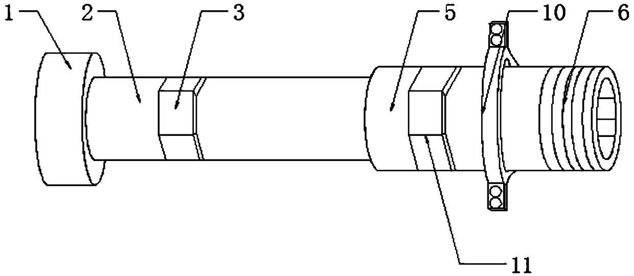
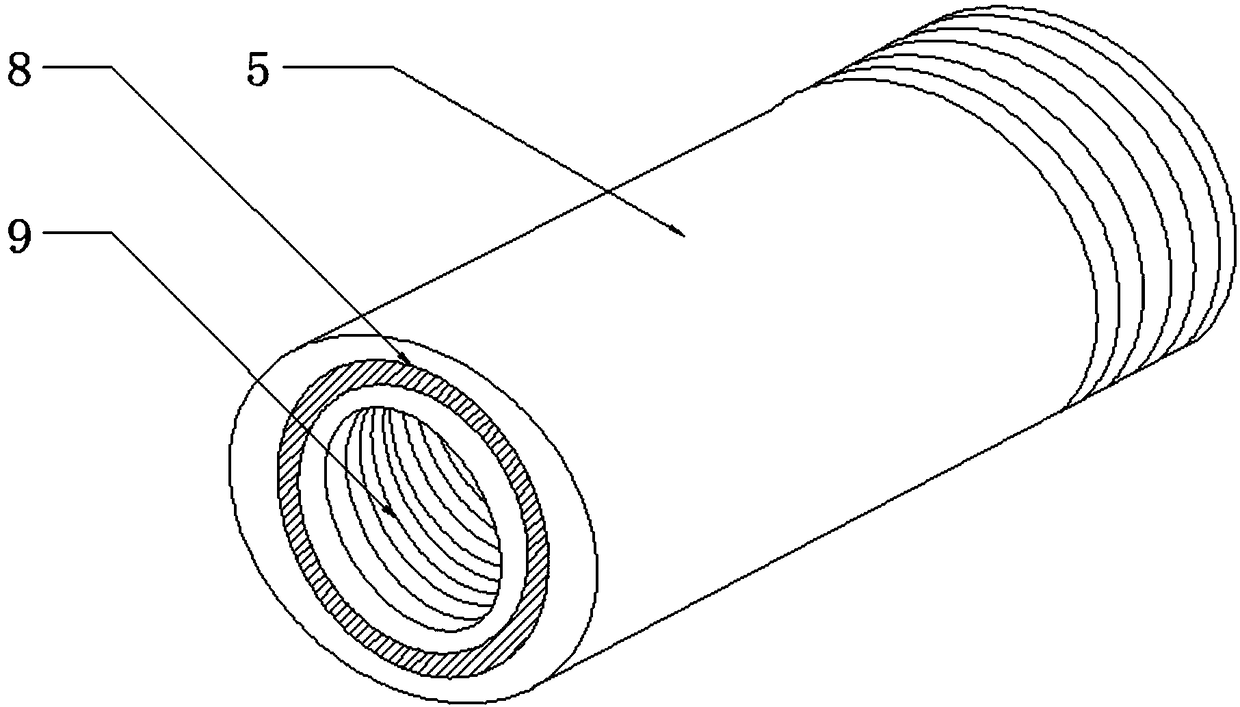
[0020] The present invention provides a kind of furnace pipe here through improvement, as Figure 1-Figure 4 As shown, it can be implemented in the following manner; a furnace tube includes a first furnace tube 2 and a second furnace tube 5, the second furnace tube 5 is arranged on one side of the first furnace tube 2, and the first furnace tube 2 Embedded in the second furnace tube 5; the surface of one end of the first furnace tube 2 is en...


PUM


Abstract

The invention discloses a furnace tube. The furnace tube comprises a first furnace tube body and a second furnace tube body, wherein the second furnace tube body is disposed on one side of the first furnace tube body, and the first furnace tube body is embedded in the second furnace tube body. One end surface of the first furnace tube body is engraved with a first thread, the inner wall of one endof the second furnace tube body is engraved with a fourth thread, and the first furnace tube body and the second furnace tube body are movably connected by the first thread and the fourth thread. A connecting tube cap is arranged at one end of the first furnace tube body, and the connecting tube cap is in communication with the first furnace tube body. The inner wall of the connecting tube cap isengraved with a third thread. One end surface of the second furnace tube body is engraved with a second thread, and a reinforcing column is arranged inside the second furnace tube body. The furnace tube has the function of convenient disassembly, can save the operating time of workers, and effectively improves the production efficiency; and an industrial furnace tube is convenient to fix to an industrial furnace, and finally the compressive capability of the industrial furnace can be further enhanced to solve the problem of bursting.

Description

technical field [0001] The invention relates to the technical field of furnace tubes, in particular to a furnace tube. Background technique [0002] The main components of industrial furnaces are: industrial furnace masonry, industrial furnace smoke exhaust system, industrial furnace preheater and industrial furnace combustion device. There are many types of industrial furnaces used in the mechanical industry. In foundry workshops, there are cupola furnaces for melting metals, induction furnaces, resistance furnaces, electric arc furnaces, vacuum furnaces, open hearth furnaces, crucible furnaces, etc.; sand drying furnaces for baking sand molds, ferroalloy Ovens and casting annealing furnaces, etc.; in the forging workshop, there are various heating furnaces for heating steel ingots or billets before forging, and heat treatment furnaces for stress relief after forging; in metal heat treatment workshops, there are various annealing methods for improving the mechanical propert...

Claims


Application Information

Patent Timeline
Patent Type & Authority Applications(China)
IPC IPC(8): F27B17/00
CPCF27B17/00
Inventor 许胜强
Owner 阜阳汇中芯自动化技术有限公司
Learn More