[0036] In order to make the objectives, technical solutions, and advantages of the present invention clearer, the present invention will be further described in detail below in conjunction with specific embodiments and with reference to the accompanying drawings. It should be understood that these descriptions are only exemplary and not intended to limit the scope of the present invention. In addition, in the following description, descriptions of well-known structures and technologies are omitted to avoid unnecessarily obscuring the concept of the present invention.
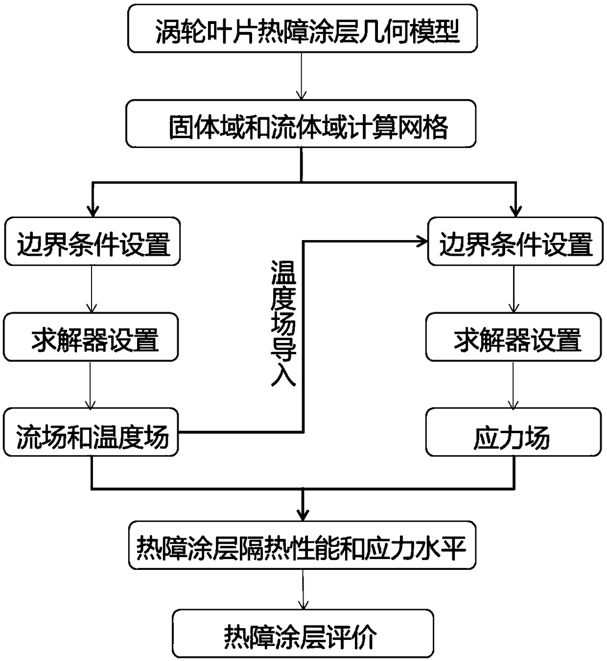
[0037] Such as figure 1 As shown, the evaluation method of the application effect of the turbine blade thermal barrier coating of the present invention includes the following steps:
[0038] (1) In the geometric modeling software, establish the geometric model of the thermal barrier coating, the geometric model of the turbine blade without thermal barrier coating, and the geometric model of the external flow field.
[0039] 1.1 In the Solidwork software, establish as figure 2 The geometric model of the external flow field is marked as FLUID and saved as .x_t format;
[0040] 1.2 In the Solidwork software, establish geometric models of thermal barrier coatings and turbine blades without thermal barrier coatings, such as image 3 , The geometric model of the thermal barrier coating is marked as TBC and saved in the .x_t format, and the geometric model of the turbine blade without thermal barrier coating is recorded as VANE and saved in the .x_t format, where the thickness of the thermal barrier coating is 0.3mm;
[0041] 1.3 Thermal barrier coating geometric model material is set to yttria stabilized zirconia; turbine blade geometric model material without thermal barrier coating is set to steel; external flow field geometric model material is set to air.
[0042] (2) According to the geometric model of the thermal barrier coating obtained in step 1, the geometric model of the turbine blade without thermal barrier coating and the geometric model of the external flow field, establish the calculation grid of thermal barrier coating without thermal barrier coating Turbine blade calculation grid and external flow field calculation grid;
[0043] 2.1 Import the geometric model of the thermal barrier coating, the geometric model of the turbine blade without thermal barrier coating and the geometric model of the external flow field into ICEM software, perform geometric Boolean merging, chamfering and geometric repair to make the surface complete and continuous ;
[0044] 2.2 Set the grid parameters according to the geometry and size to refine the grid of the thermal barrier coating calculation domain. Because the thickness of the thermal barrier coating is much smaller than the thickness of the turbine blade without thermal barrier coating, in order to improve the quality of the grid, The grid of the thermal barrier coating needs to be refined, and 5 boundary layers are divided at the fluid-solid interface. The fluid-solid interface refers to the outer wall surface where the thermal barrier coating contacts the airflow.
[0045] 2.3 Give each calculation grid a corresponding name. The thermal barrier coating calculation grid is marked as TBC, the geometric model of the turbine blade without thermal barrier coating is marked as VANE, and the external flow field geometric model is marked as FLUID. Give the calculation grid Each boundary entrance, exit, blade surface, and periodic interface are respectively named and exported as a grid in .cfx5 format. The contact surface of the turbine blade and the thermal barrier coating is named i-tbc, and the outer surface of the thermal barrier coating is named s- tbc.
[0046] (3) According to the thermal barrier coating calculation grid, the calculation grid of the turbine blade without thermal barrier coating, and the external flow field calculation grid, define the material parameters of the thermal barrier coating, set the solution boundary conditions, and proceed Iterative calculation to obtain the temperature field distribution of two calculation domains of thermal barrier coating and turbine blade without thermal barrier coating;
[0047] 3.1 Import the three .cfx5 format grid models obtained in step 2 into Ansys CFX software, and check the grid;
[0048] 3.2 Definition Thermal barrier coating material is set to yttria-stabilized zirconia. Its parameters are shown in Table 1, including density, thermal conductivity, viscosity coefficient, specific heat capacity, thermal expansion coefficient; turbine blade geometry model material without thermal barrier coating Set to steel; the material of the external flow field geometry model is set to air. The shear stress transport turbulence model and the non-equilibrium near-wall model are used to define the boundary conditions including the pressure and temperature of the inlet and outlet of the main flow, the pressure and temperature of the cold air inlet, and the coupled heat transfer and periodic boundary conditions of the wall, as shown in Table 2. . Set 1200 iterative steps to solve, wait for the result to converge to less than 10 -5 Then get the steady state result;
[0049]
[0050] Table 1 Parameter map of yttria stabilized zirconia
[0051]
[0052] Table 2 Flow field boundary conditions parameter diagram
[0053] 3.3 Analyze the calculation results in the previous step and confirm the convergence, export the temperature field distribution of the two calculation domains of the thermal barrier coating and the turbine blade without thermal barrier coating, and save them as T_tbc.csv and T_vane.csv files.
[0054] (4) According to the temperature field distribution of the thermal barrier coating calculation domain and the thermal barrier coating calculation grid, set the solution boundary conditions and material parameters, and perform iterative calculations to obtain the thermal barrier coating stress field distribution, and obtain the thermal barrier The maximum principal stress and maximum shear stress data of the coating stress field;
[0055] 4.1 Import the thermal barrier coating calculation grid into Ansys finite element analysis software, and import the thermal barrier coating temperature field obtained in the previous step into the grid through interpolation;
[0056] 4.2 Set as a linear elastic solution model, considering thermal stress; define material parameters including density, elastic modulus, Poisson's ratio, thermal conductivity, and specific heat capacity, and set boundary conditions for solution calculation;
[0057] 4.3 Analyze the calculation results in the previous step, and after confirming the convergence, export the maximum principal stress and maximum shear stress of the thermal barrier coating stress field, and save the data as Stress_principal.csv and Stress_shear.csv files.
[0058] (5) According to the temperature field distribution of the two calculation domains of the thermal barrier coating and the turbine blade without thermal barrier coating, and the maximum principal stress and maximum shear stress data of the thermal barrier coating stress field, The preset calculation program calculates to obtain the thermal barrier efficiency of the thermal barrier coating, and obtain the local comprehensive and global comprehensive evaluation factors of the thermal barrier coating.
[0059] 5.1 Extract the surface temperature of the corresponding position in the temperature field of the two calculation domains of the thermal barrier coating and the turbine blade without the thermal barrier coating, and subtract the temperature at the corresponding position to obtain the thermal barrier coating's thermal insulation performance;
[0060] 5.2 Extract data from Stress_principal.csv and Stress_shear.csv files to obtain the maximum principal stress and maximum shear stress of the thermal barrier coating interface;
[0061] 5.3 Establish the following Y as the evaluation factor of the thermal barrier coating, input the thermal insulation efficiency and the maximum principal stress of the thermal barrier coating, and use the self-edited Python program to calculate the local comprehensive and global comprehensive evaluation factors of the thermal barrier coating. Calculated as follows;
[0062]
[0063]
[0064] Y is the local comprehensive evaluation factor of the thermal barrier coating, Y T It is the global comprehensive evaluation factor of the thermal barrier coating, S represents the surface area of the blade, and w is the risk coefficient. The value is determined for different positions through experiments. Here, considering the curvature of the leading edge and trailing edge of the blade and the serious erosion, the selection of experience Such as Figure 4 The function. T tbc , T notbc Is the surface temperature of the blade with or without thermal barrier coating, σ max Is the material strength of the thermal barrier coating, T ∞ Refers to the gas inlet temperature, T c It refers to the cooling gas temperature, and σ refers to the maximum local principal stress and maximum shear stress.
[0065] The obtained local comprehensive evaluation factor of the thermal barrier coating and the global comprehensive evaluation factor of the thermal barrier coating simultaneously reflect the thermal insulation effect and stress level of the thermal barrier coating. A comprehensive evaluation factor is used to evaluate the thermal barrier coating. An evaluation of the overall performance of the layer is of great significance to the design and optimization of the thermal barrier coating. The range of the obtained value is less than 1, the larger the value, the better the heat insulation effect, the lower the stress level, the higher the comprehensive evaluation, the smaller the value, the worse the comprehensive evaluation, when the value is negative, it means that the coating will peel off locally .
[0066] In the formula, the value of the risk coefficient of w is obtained by the following formula:
[0067] w(x s ,z)=1-b[|sin(πz)cos(2πx s )|+sin(πz)cos(2πx s )) (3)
[0068] In the formula, b is a risk factor, z represents leaf height, x s Indicates the position of the chord length of the blade, which is determined by experiment; the risk of different positions is different in engineering, so in order to obtain a global evaluation factor, the basic evaluation Y is multiplied by a weight w, and w needs to be based on The engineering experience takes different values, and the blade w under different working conditions is different. Equation 3 is based on a certain experimental experience.
[0069] Such as Figure 4 For the surface temperature cloud map of the blade with and without thermal barrier coating, it can be found that the thermal barrier coating significantly reduces the temperature of the blade and reduces the temperature gradient of the blade;
[0070] Such as Figure 5 It is a broken line graph of the heat insulation efficiency of the thermal barrier coating on the middle chord. The abscissa -1 to 1 in the figure indicate the chord relative position from the trailing edge-pressure surface-leading edge-suction surface-trailing edge. It can be seen that the thermal barrier coating has poor thermal insulation efficiency at the leading edge and pressure surface, about 20K, and the thermal insulation efficiency at the trailing edge is basically greater than 60K.
[0071] Such as Image 6 Is the maximum principal stress of the thermal barrier coating on the outer surface of the thermal barrier coating and the middle chord line of the contact surface of the turbine blade and the thermal barrier coating. It can be seen that the thermal barrier The maximum principal stress of the coating is greater than the maximum principal stress of the mid-string thermal barrier coating on the outer surface of the thermal barrier coating, and the stress is higher at the air film hole.
[0072] Such as Figure 7 It is a broken line graph of the comprehensive evaluation factor of the thermal barrier coating on the mid-string, combined with formula (1), it can be seen from the figure: a. The thermal barrier coating is smaller at the leading edge and its vicinity, which is due to the leading edge thermal barrier The coating has poor thermal insulation performance and high thermal stress, so its comprehensive performance is not good; b. It has good thermal insulation performance at the trailing edge and the stress value is not high, so the comprehensive evaluation is good; c. Although the middle part of the pressure surface has the highest heat insulation efficiency, its stress level is also higher, so its evaluation is not the highest; it can also be obtained that when b = 0.5, Yt = 0.01684, this parameter can be used to compare the global application of different thermal barrier coatings The effect is to facilitate the optimal design of the thermal barrier coating in engineering. Therefore, this evaluation method can simultaneously consider the thermal barrier coating’s thermal insulation performance and stress level to obtain an evaluation of the comprehensive performance of the thermal barrier coating. The value is of great significance to the design and optimization of thermal barrier coatings.
[0073] This example solves the thermal insulation performance and thermal stress of the turbine blade thermal barrier coating. The thermal barrier coating’s thermal insulation performance and stress level can be considered at the same time, and the comprehensive performance of the thermal barrier coating can be evaluated. The actual turbine engine operating conditions are far more complicated than this. Using this method to simulate and evaluate thermal barrier coatings in more complex environments is of great significance to the engineering design and optimization of thermal barrier coatings.