Compressor and manufacturing method thereof

A manufacturing method and compressor technology, applied in the direction of manufacturing tools, mechanical equipment, machines/engines, etc., can solve the problems of increased noise, poor performance, damage to assembly accuracy, etc., and achieve uniform air gap, reduced noise, and improved performance. better effect

Pending Publication Date: 2019-03-12
SHANGHAI HITACHI ELECTRICAL APPLIANCES CO LTD
View PDF0 Cites 4 Cited by
  • Summary
  • Abstract
  • Description
  • Claims
  • Application Information

AI Technical Summary

Problems solved by technology

However, this method will destroy the original assembly accuracy due to welding deformation, r

Method used


Image

  • Compressor and manufacturing method thereof
  • Compressor and manufacturing method thereof
  • Compressor and manufacturing method thereof

Examples


Embodiment Construction

[0054] Example embodiments will now be described more fully with reference to the accompanying drawings. Example embodiments may, however, be embodied in many forms and should not be construed as limited to the embodiments set forth herein. Rather, these embodiments are provided so that this disclosure will be thorough and complete, and will fully convey the concept of the example embodiments to those skilled in the art. The same reference numerals denote the same or similar structures in the drawings, and thus their repeated descriptions will be omitted.

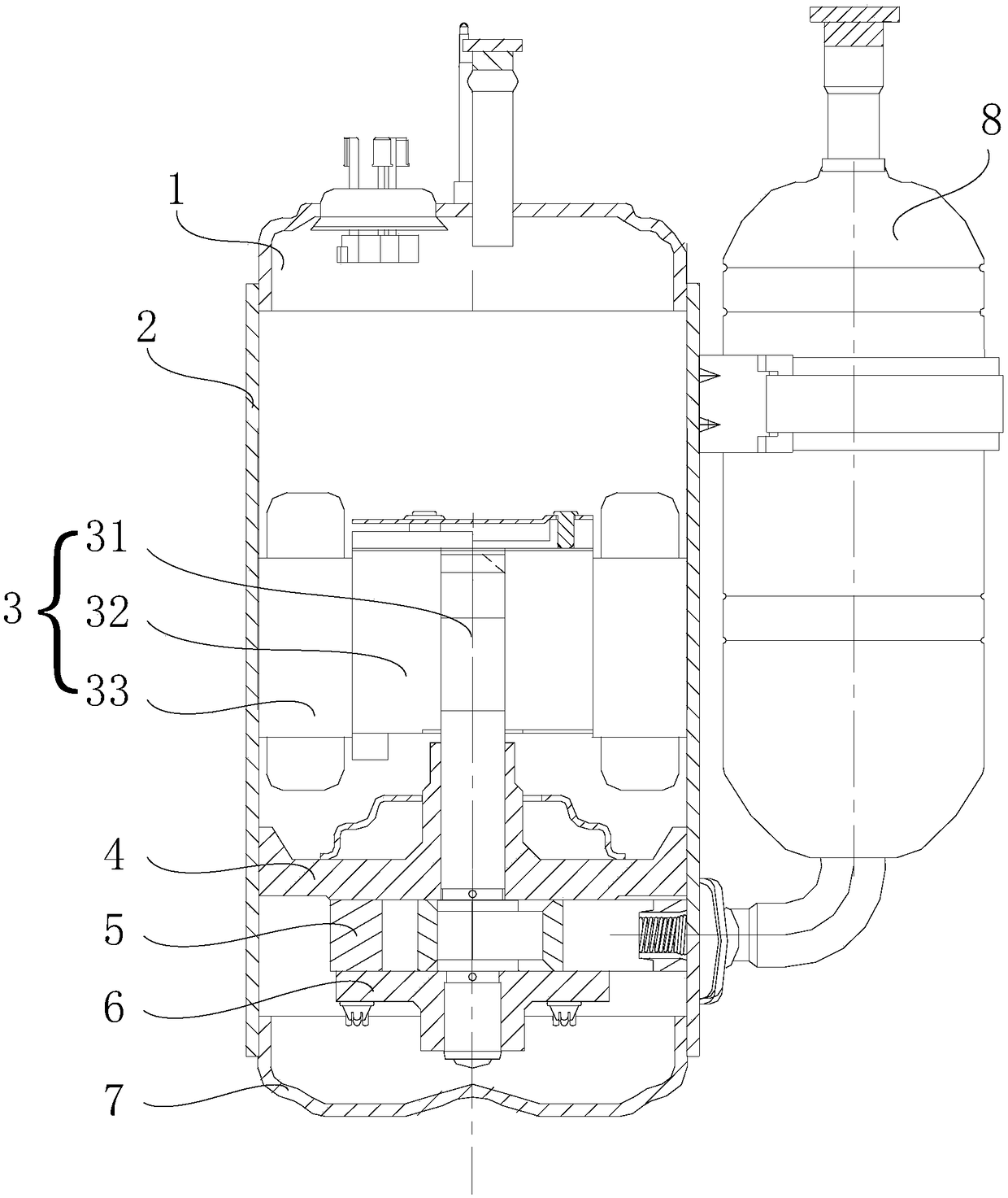
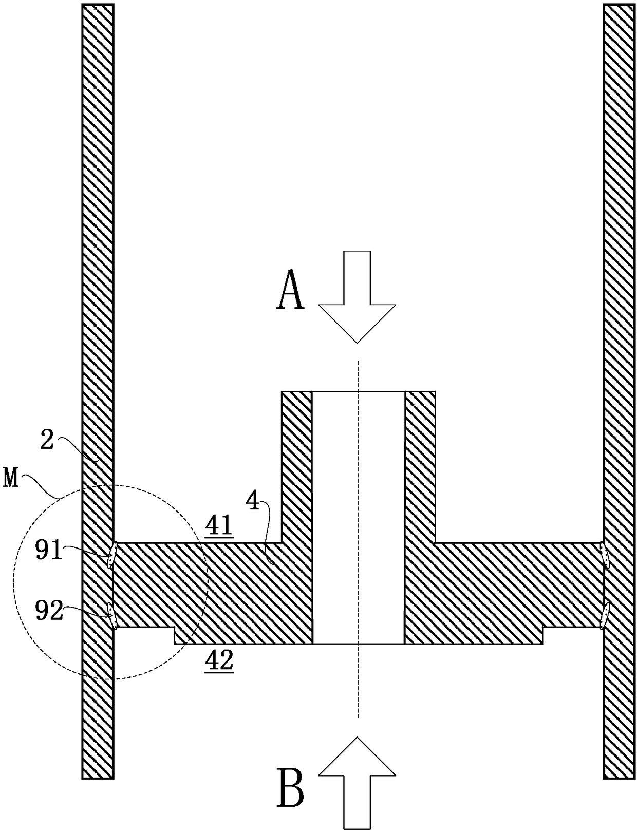
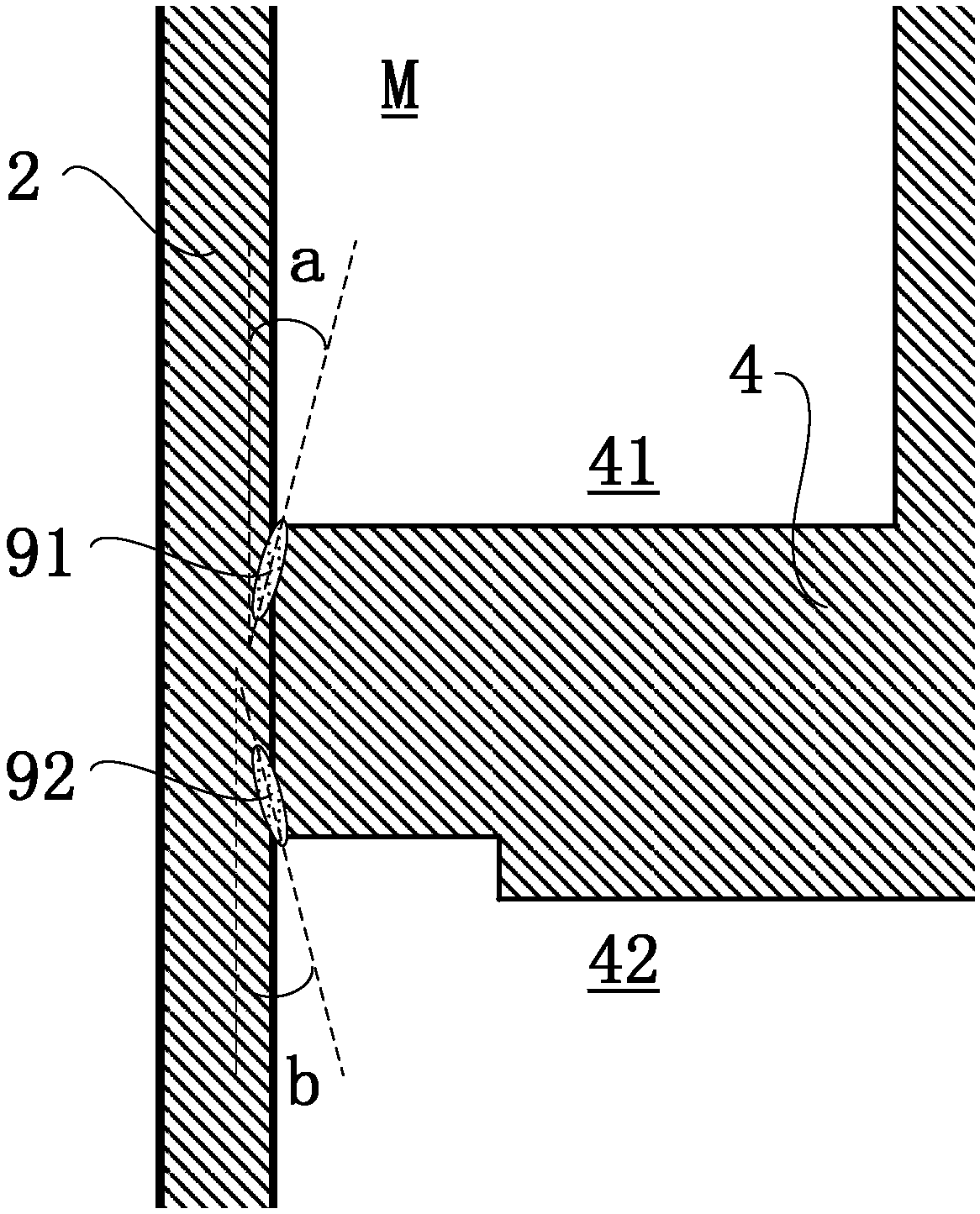
[0055] figure 1 It is a cross-sectional view of the compressor of the present invention. figure 2 It is a schematic diagram of the welding of the upper cylinder head and the inner wall of the casing in the compressor in the first embodiment of the present invention. Such as Figures 1 to 2 The compressor of the present invention shown includes: an upper cover 1 , a casing 2 , a motor 3 , an upper cylinder cover 4 , a c...


PUM

PropertyMeasurementUnit
Penetrationaaaaaaaaaa

Abstract

The invention provides a compressor and a manufacturing method thereof. The compressor comprises a shell, a motor, an air cylinder, a crankshaft, an upper cylinder cover and a lower cylinder cover. The motor and the air cylinder are contained in the shell. The crankshaft transmits rotation force of the motor to a piston in the air cylinder so as to compress a refrigerant. Compression space is jointly defined by the upper cylinder cover, the lower cylinder cover and the air cylinder, and the crankshaft is supported. The upper cylinder cover is located between the motor and the air cylinder, theupper cylinder cover is provided with a through hole for the crankshaft to penetrate, and the upper cylinder cover is provided with a first side facing the motor and a second side facing the air cylinder. The inner wall of the shell is in laser fusion joint with the periphery of the first side of the upper cylinder cover and/or the periphery of the second side, and the included angle formed by the axial direction of the fusion joint welding point and the inner wall of the shell ranges from 0 degree to 45 degrees. According to the compressor and the manufacturing method thereof, the original assembling precision cannot be damaged even when welding deformation happens, accordingly, it can be guaranteed that stator and rotor air gaps are uniform, noise is lowered, and performance becomes good.

Description

technical field [0001] The invention relates to the field of refrigeration equipment, in particular to a rolling rotor compressor and a manufacturing method thereof. Background technique [0002] In general, a hermetic compressor includes a motor for generating a driving force in an inner space of a hermetically sealed case, and a compression part coupled to the motor for compressing refrigerant. Hermetic compressors can be classified into reciprocating compressors, scroll compressors, and rolling rotor compressors according to different refrigerant compression mechanisms. Reciprocating compressors, scroll compressors, and rolling rotor compressors all utilize the rotational force of an electric motor. [0003] Most of the existing rolling rotor compressors are assembled into the pump body (mainly including: crankshaft, piston, cylinder, upper and lower cylinder heads, blades, etc.) after the parts are processed, and then welded by three-point / six-point way, connect the sh...

Claims


Application Information

Patent Timeline
IPC IPC(8): F04C23/02F04C29/00F04C29/06
CPCF04C23/02F04C29/00F04C29/06B23K26/21F04C18/356F04C23/008F04C2230/231B23K2101/04F04B9/02F04B53/006F04B53/14F04B53/16B23K26/22B23K26/282B23K26/28Y10T29/49945B23K26/206B23K26/24B23K26/242B23K26/20F04C18/02F04C18/04B23P15/00F04C2230/60
Inventor 黄波赵凤荣汤轶群
Owner SHANGHAI HITACHI ELECTRICAL APPLIANCES CO LTD
Why Eureka
Try Eureka