Laser line scanning 3D detection method and system based on scanning galvanometer and event camera

A technology of scanning galvanometer and detection method, which is applied in the direction of measuring device, optical device, instrument, etc., can solve the problems of high computing performance of processing chip, low resolution of depth image, high algorithm complexity, etc., and achieve fast data transmission speed, The effect of simple algorithm and fast response

Active Publication Date: 2019-03-12
XI AN ZHISENSOR TECH CO LTD
View PDF5 Cites 15 Cited by
  • Summary
  • Abstract
  • Description
  • Claims
  • Application Information

AI Technical Summary

Problems solved by technology

[0003] 1. The depth information of the binocular solution relies on a pure software algorithm. This algorithm is highly complex and difficult, and the processing chip requires high computing performance. It is not applicable in dark environments and when the features are not obvious.
[0004] 2. The depth image resolution of the structured light solution can be made relatively high, but it is easily affected by light, and the outdoor environment is basically unusable; moreover, multiple photos are required to complete encoding and decoding, which greatly reduces the detection rate, and is only suitable for measuring static objects. , not suitable for measuring dynamic objects
[0005] 3. The TOF solution has good anti-interference performance and a wider viewing angle, but the resolution of the depth image is very low. It can be used for some simple obstacle avoidance and visual navigation, but it is not suitable for high-precision occasions.

Method used


Image

  • Laser line scanning 3D detection method and system based on scanning galvanometer and event camera
  • Laser line scanning 3D detection method and system based on scanning galvanometer and event camera
  • Laser line scanning 3D detection method and system based on scanning galvanometer and event camera

Examples


Embodiment 1

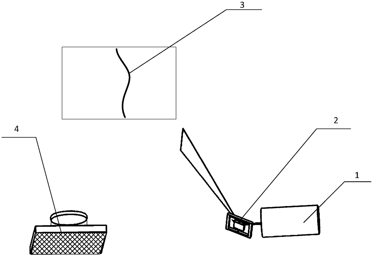
[0067] Such as figure 1 As shown, the laser line scanning 3D detection system based on the scanning galvanometer and the event camera in this embodiment mainly includes a line laser 1, a scanning galvanometer 2 and an event camera 4. The line laser 1 continues to work and is incident on the scanning galvanometer 2. The direction of the laser line is consistent with the direction of the rotation axis of the scanning galvanometer 2, and the scanning galvanometer 2 rotates around its rotation axis to reflect the line laser to the object 3 to be measured to realize laser line scanning; the event camera 4 collects the reflected light from the object 3 to be measured The laser line signal information realizes the 3D detection of the object 3 to be measured, and the detection method is as follows:

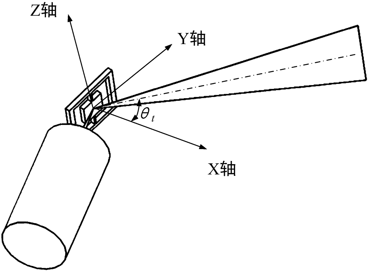
[0068] The motion of scanning galvanometer 2 is:

[0069] Among them, θ t is the rotation angle of the scanning galvanometer at time t, A is the amplitude of the rotation angle of the...

Embodiment 2

[0086] The resonant scanning galvanometer has high reliability, requires a small driving force, and has a large rotation angle, and is often used in the laser scanning process. Although the response rate of the event camera is extremely fast, it is limited after all. If the scanning frequency of the scanning galvanometer is too high, the accuracy may be reduced, such as Figure 4 , t n and t n+1 are two time periods that the event camera can continuously distinguish, and the scanned areas are respectively i n and i n+1 , if multiple rows of pixels respond at the same time in each time period, that is, at time t n and t n+1 Equivalent to fringe scans, no longer laser line scans, event cameras can no longer accurately detect t n and t n+1 The details of the fringe area scanned by the scanning galvanometer during the time period.

[0087] This embodiment proposes a method to solve the problem of low 3D detection accuracy caused by the above reasons: control the output of t...


PUM


Abstract

The invention belongs to the field of 3D detection and measurement, and particularly relates to a laser line scanning 3D detection method and system based on a scanning galvanometer and an event camera. The method comprises the following steps: the laser line is reflected to an object to be detected by the scanning galvanometer, so that laser line scanning is achieved; the event camera is adoptedto collect laser line signal information reflected from the object to be measured, and pixel points with changed brightness on the object to be measured and corresponding time points are stored and output; the position coordinate of the space point of the object to be detected scanned by the laser line at the moment is calculated through the relative position between the scanning galvanometer andthe event camera, the pixel point output in the step 2 and the scanning galvanometer rotation angle corresponding to the moment point corresponding to the pixel point; the steps are repeated to complete all space point coordinates of the object to be measured so as to obtain 3D point cloud data of the object to be measured, thereby solving the limitations of frame rate, resolution and illuminationresistance in the current 3D scheme.

Description

technical field [0001] The invention belongs to the field of 3D detection and measurement, in particular to a laser line scanning 3D detection method and system based on a scanning galvanometer and an event camera. Background technique [0002] With the rapid development of machine vision, intelligent manufacturing, security and logistics, non-contact rapid 3D reconstruction technology has become a major research hotspot. The current mainstream 3D solutions are mainly binocular RGB solutions, structured light solutions, and TOF solutions. The three solutions have limitations in frame rate, resolution, and anti-light performance: [0003] 1. The depth information of the binocular solution relies on a pure software algorithm. This algorithm is highly complex and difficult, and the processing chip requires high computing performance. It is not applicable in dark environments and when the features are not obvious. [0004] 2. The depth image resolution of the structured light s...

Claims


Application Information

Patent Timeline
IPC IPC(8): G01B11/00
CPCG01B11/002G01B11/2518
Inventor 夏长锋宋秀敏杨迪乔大勇何伟
Owner XI AN ZHISENSOR TECH CO LTD
Why Eureka
Try Eureka