A method for calculate nonlinear load of flying-wing unmanned aerial vehicle
A load calculation and nonlinear technology, applied in the field of flying-wing UAV, can solve the problem that the nonlinear load calculation method of flying-wing UAV is not disclosed.
- Summary
- Abstract
- Description
- Claims
- Application Information
AI Technical Summary
Problems solved by technology
Method used
Image
Examples
Embodiment 1
[0054] A non-linear load calculation method for flying wing UAV, such as Figure 6 As shown, it mainly includes the following steps:
[0055] Step S101: Solving the flight attitude parameters: based on the aerodynamic nonlinear coefficients, the multi-degree-of-freedom coupling flight dynamics simulation model is used to calculate the aerodynamic force and dynamic flight of the aircraft, and at the same time establish the objective function, and use the optimization algorithm to solve the problems that do not meet the requirements. The results of the flight attitude parameters are optimized, and the output flight attitude parameters are used as the input of the nonlinear concentrated load calculation;
[0056] Step S102: Calculation of non-linear concentrated loads: the aerodynamic data of the geometric shape components of the aircraft, the flight attitude parameters, and the mass data of the components are used as input, and the aerodynamic loads and inertia of the components...
Embodiment 2
[0060] This embodiment is optimized on the basis of Embodiment 1. In the non-linear load calculation method based on the rudder surface coefficient increment in the step S102, the flight load after the balance of the whole machine and components should be the aerodynamic force that just produces the flight attitude. ; The data interface is the nonlinear coefficient of the stabilizer base and the nonlinear increment of each rudder surface. The calculation formula of the load of the components is as follows:
[0061] C i Wing = C i Wing (M, α, δ=0) + ΔC i Wing (M, α, δ i )+..+ΔC n Wing (M, α, δ n )
[0062] +C i Wing rudder i(M, α, δ i )+·..+C i Wing rudder n(M, α, δ n )
[0063] Among them, M, α, δ 1 ,δ 2 ,,,δ n as the dependent variable.
[0064] The establishment of nonlinear flight load calculation method mainly includes the following two aspects:
[0065] (1) Logical design of flight load calculation of the whole aircraft and components:
[0066] Such as i...
Embodiment 3
[0073] The present embodiment optimizes on the basis of embodiment 2, mainly comprises the following steps:
[0074] 1. Analysis of the aerodynamic characteristics of multiple control surfaces in the aerodynamic layout of the flying wing UAV
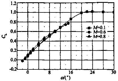
[0075] The aerodynamic layout of a typical flying-wing multi-control surface UAV is shown in figure 1 , the aerodynamic characteristics and rudder effect increment of the UAV with flying wing layout have obvious nonlinear characteristics. When the aircraft performs extreme maneuvers, there will often be a nonlinear section with a large angle of attack and a large rudder deflection angle. See figure 2 .
[0076] 2. Establish a high-precision nonlinear multi-degree-of-freedom aerodynamic coefficient mathematical model
[0077] In the step S101, a nonlinear multi-degree-of-freedom aerodynamic coefficient mathematical model is established, wherein the longitudinal aerodynamic coefficient calculation formula is as follows:
[0078] C i =...
PUM
 Abstract
Description
Claims
Application Information
 - R&D
- Intellectual Property
- Life Sciences
- Materials
- Tech Scout
- Unparalleled Data Quality
- Higher Quality Content
- 60% Fewer Hallucinations
Browse by: Latest US Patents, China's latest patents, Technical Efficacy Thesaurus, Application Domain, Technology Topic, Popular Technical Reports.
© 2025 PatSnap. All rights reserved.Legal|Privacy policy|Modern Slavery Act Transparency Statement|Sitemap|About US| Contact US: help@patsnap.com


