Tool magazine device for fixed beam-type gantry multi-spindle machine tool, machine tool and tool change method
A multi-spindle and machine tool technology, applied in positioning devices, metal processing machinery parts, clamping, etc., can solve problems such as space conflicts, narrow spacing, and complex structures
- Summary
- Abstract
- Description
- Claims
- Application Information
AI Technical Summary
Problems solved by technology
Method used
Image

Examples
Embodiment 1
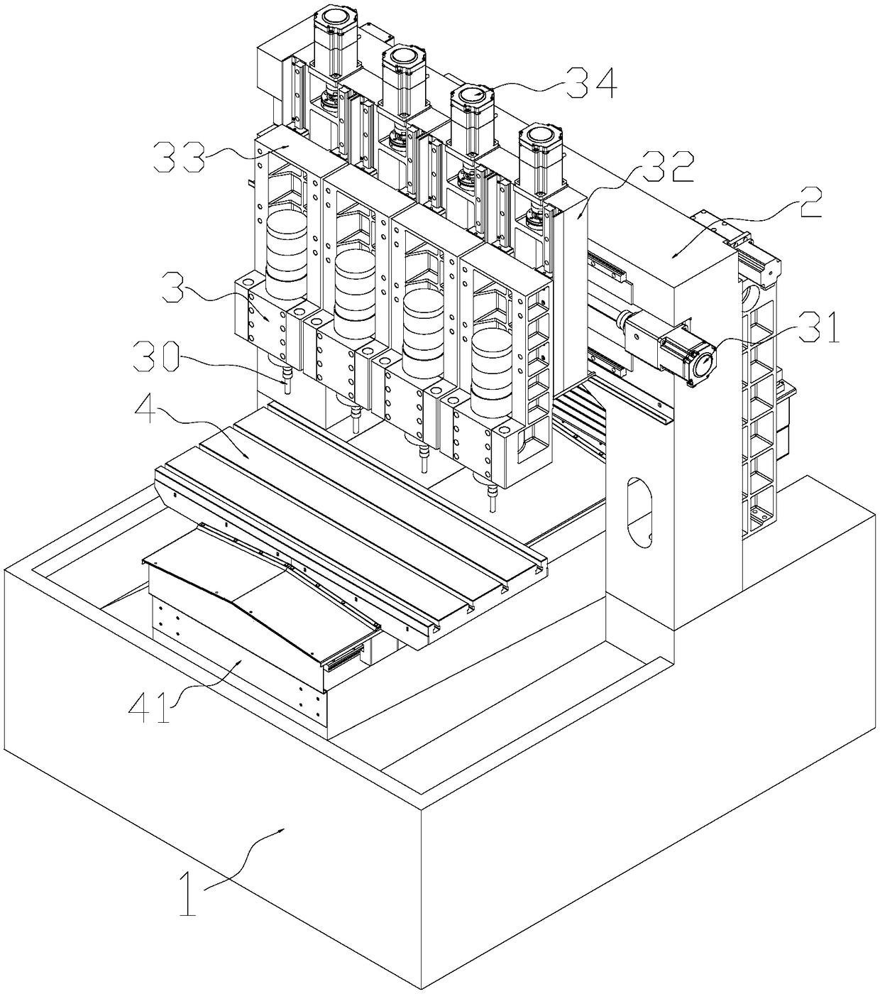
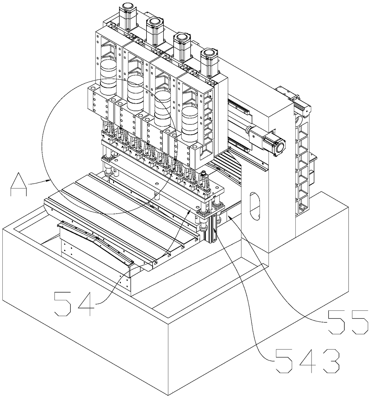
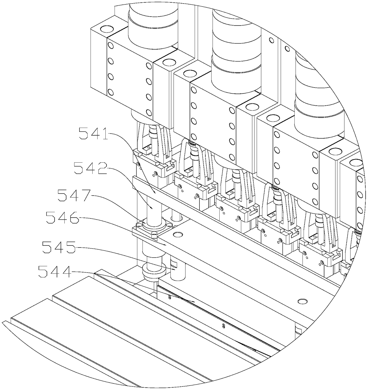
[0076] The embodiment of the present invention provides a fixed-beam type gantry multi-spindle machine tool. The machine tool gantry of the fixed-beam type gantry machine tool is fixed, and the spindle moves on the fixed-beam type gantry to cooperate with the movable workbench to complete the processing, which is different from the moving beam type structure or other non- Fixed beam structure, this embodiment is limited to the introduction of fixed beam structure, combined with Figure 1 to Figure 6 As shown, it includes: machine bed 1, on which a fixed-beam machine tool gantry 2 is arranged, and the front side of the machine tool gantry 2 is equipped with a multi-spindle 3 that can move along the left and right directions and up and down directions of the machine tool. The main shaft refers to that the number of main shafts is greater than one, that is, more than two main shafts are called multi-spindles. Longitudinal driving motor 34 cooperates with the drive of the screw as...
Embodiment 2
[0099] This embodiment is an improvement made in the above-mentioned embodiment 1, specifically: the arrangement of multiple cutter head mounts in the matrix tool magazine is: the cutter head mounts are arranged along the left and right directions, and each spindle corresponds to more than two cutters The head mounting seat forms a row-type tool magazine; the tool holders in the tool holder group are arranged along the left and right directions, and every two tool holders correspond to a main shaft; the tool change drive module includes a drive to enable the tool holder to move horizontally relative to the tool holder to achieve The tool holder selects the first horizontal driving assembly of the cutter head mounting seat in the left and right direction and the first vertical driving assembly for driving the tool holder to move up and down relative to the cutter head mounting seat or the main shaft to realize the insertion and removal of the cutter head of the tool holder.
[0...
Embodiment 3
[0105] Compared with the above-mentioned embodiment 1, this embodiment makes changes to the arrangement of the tool head mounting seats in the tool magazine and the arrangement of the tool holders in the tool holder group. Such as Figure 7 , Figure 8 shown.
[0106] The arrangement of multiple cutter head mounts 521 in the matrix tool magazine is as follows: the cutter head mounts 521 are arranged along the front and rear directions, and each spindle 3 corresponds to at least one row of cutter head mounts 521, and the number of cutter head mounts 521 in each row is 2 More than 4 tool magazines are formed, for example, 4 spindles correspond to at least 4 rows of tool head mounting seats (in each embodiment, it is defined as: horizontal rows and vertical columns); every two tool holders in the tool holder group 530 respectively in a row corresponding to one spindle 3; if 4 spindles correspond to 4 rows of cutter head mounting seats, the number of cutter head mounting seats i...
PUM
 Abstract
Description
Claims
Application Information
 - R&D
- Intellectual Property
- Life Sciences
- Materials
- Tech Scout
- Unparalleled Data Quality
- Higher Quality Content
- 60% Fewer Hallucinations
Browse by: Latest US Patents, China's latest patents, Technical Efficacy Thesaurus, Application Domain, Technology Topic, Popular Technical Reports.
© 2025 PatSnap. All rights reserved.Legal|Privacy policy|Modern Slavery Act Transparency Statement|Sitemap|About US| Contact US: help@patsnap.com