
Oil cylinder fast movement device and control mode

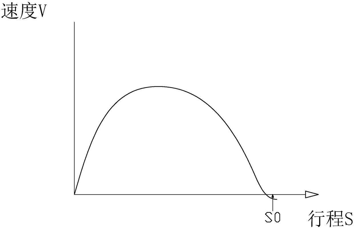
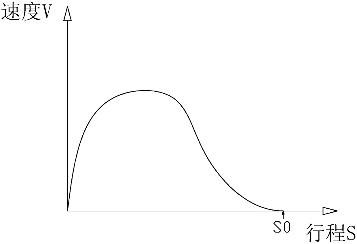
A fast-moving, oil-cylinder technology, used in fluid pressure actuating devices, fluid pressure actuating system testing, servo motors, etc., can solve problems such as longer movement time of oil cylinders, difficulty in stopping accurate stops, and rapid changes in servo pump displacement. Achieve the effect of simple structure, precise and controllable piston rod position, and short movement period

Active Publication Date: 2019-03-15
DONGHUA MACHINERY
View PDF8 Cites 0 Cited by
  • Summary
  • Abstract
  • Description
  • Claims
  • Application Information

AI Technical Summary

Problems solved by technology

The servo motor pump is used as the power unit to drive the cylinder to move. In the process of high-speed movement, because the servo motor rotates at a high speed, it is very difficult to achieve the force balance at both ends of the piston rod of the cylinder during the rapid stop process, so that the position of the piston rod stops accurately. Because of the servo motor Rapid braking or even reverse rotation will cause the displacement of the servo pump to change rapidly and even the oil pipe will suck back the vacuum, which will easily lead to the fluctuation and offset of the stop position of the piston rod, such as figure 1 shown
The servo motor pump unit starts to decelerate a long distance before the stop position of the cylinder to control the stop precision of the piston rod, but this control will cause the cylinder to move longer, such as figure 2 shown
[0003] In order to realize the precise control of the stop position of the oil cylinder during the fast movement, some people often use the servo valve to control the movement of the oil cylinder piston, which invisibly increases a lot of cost and wastes the sensitive characteristics of the servo motor drive. The valve has good position control accuracy during the high-speed movement of the servo motor pump unit as the power unit. How to solve the above problems has become an urgent problem to be solved

Method used


Image

  • Oil cylinder fast movement device and control mode
  • Oil cylinder fast movement device and control mode
  • Oil cylinder fast movement device and control mode

Examples


Embodiment Construction

[0030] The present invention will be further described in detail below in conjunction with the embodiments in the accompanying drawings.

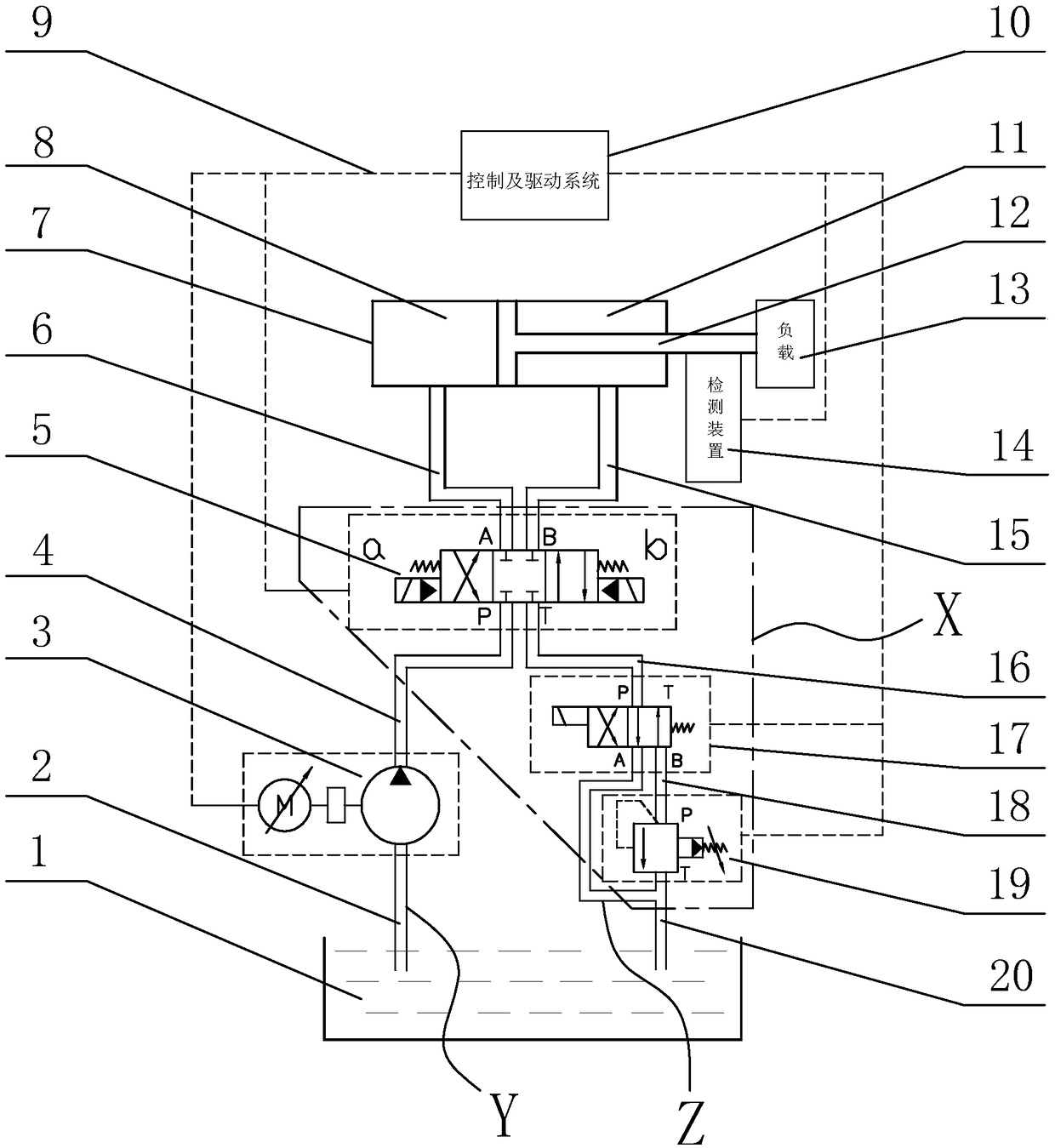
[0031] like image 3 As shown, the oil cylinder rapid movement device of the present invention includes a fuel tank 1, a servo motor pump unit 3, a pipeline structure X, a direction control mechanism Y, and a load 13, wherein a piston rod 12 is arranged in the oil cylinder 7, and the piston rod 12 divides the oil cylinder into 7 points. The rod chamber 11 and the rodless chamber 8, the load 13 is fixed on the piston rod 12, the oil tank 1, the servo motor pump unit 3, the direction control mechanism Y, the rodless chamber 8, and the rod chamber 11 pass through the pipeline structure X connection, it is characterized in that: the oil cylinder rapid movement device is provided with a control and drive system 10 and a detection device 14, and the detection device 14 is fixed on the piston rod 12 to detect the moving position of the piston rod ...


PUM


Abstract

The invention discloses an oil cylinder fast movement device and control mode. The device comprises an oil tank, a servo motor pump unit, a pipeline structure, a direction control mechanism and a load, wherein a piston rod is arranged in an oil cylinder and divides the oil cylinder into a rod cavity and a rod-free cavity, the load is fixed on the piston rod, the oil tank, the servo motor pump unit, the direction control mechanism, the rod-free cavity and the rod cavity are connected through the pipeline structure, the device is further provided with a control and driving system and a detectiondevice, the detection device is fixed on the piston rod and is used for detecting the moving position of the piston rod on the oil cylinder, the control and driving system controls the action of theservo motor pump unit, the action of the direction control mechanism and the action of the detection device through control signal lines; and according to the oil cylinder fast movement control mode,the control and driving system is used for controlling the direction control mechanism to achieve corresponding action. According to the oil cylinder fast movement device and control mode, the structure of the device is simple, the movement period is short, the movement of the piston rod is fast, the operation is smooth and stable, and the stop position of the piston rod is accurate and controllable.

Description

technical field [0001] The invention relates to the technical field of mechanical equipment hydraulic cylinder control, in particular to a motion device and a control method that uses a servo motor pump unit as a power unit to rapidly drive an oil cylinder to move. Background technique [0002] At present, with the maturity and popularization of servo energy-saving technology, the mainstream hydraulic power unit on the market has gradually transitioned from the previous fixed-displacement pump with asynchronous motor drive to the servo motor pump as the power unit drive. As a hydraulic actuator-hydraulic cylinder assembly commonly used in hydraulic equipment, its control efficiency and accuracy have been further improved with the advancement of hydraulic technology. The hydraulic oil pressure and flow of conventional asynchronous motor-driven fixed-displacement pumps are realized by pressure valves and flow valves. The stopping accuracy of the piston rod of the hydraulic cyl...

Claims


Application Information

Patent Timeline
Patent Type & Authority Applications(China)
IPC IPC(8): F15B11/08F15B13/02F15B19/00
CPCF15B11/08F15B13/02F15B19/00F15B2211/20515F15B2211/20569F15B2211/857
Inventor 谢雄飞蔡国强
Owner DONGHUA MACHINERY
Learn More