
Optical signal-to-noise ratio monitoring device and optical signal-to-noise ratio monitoring method

A technology for optical signal-to-noise ratio and monitoring devices, which is applied in electromagnetic wave transmission systems, instruments, character and pattern recognition, etc., can solve problems such as cost impact, and achieve the effects of low cost, fast monitoring speed and high accuracy

Active Publication Date: 2019-03-15
UNIV OF SCI & TECH BEIJING
View PDF7 Cites 4 Cited by
  • Summary
  • Abstract
  • Description
  • Claims
  • Application Information

AI Technical Summary

Problems solved by technology

The cost of the OPM module is directly related to the monitoring technology, and different receiving methods and data processing algorithms will affect the cost

Method used


Image

  • Optical signal-to-noise ratio monitoring device and optical signal-to-noise ratio monitoring method
  • Optical signal-to-noise ratio monitoring device and optical signal-to-noise ratio monitoring method
  • Optical signal-to-noise ratio monitoring device and optical signal-to-noise ratio monitoring method

Examples


Embodiment 1

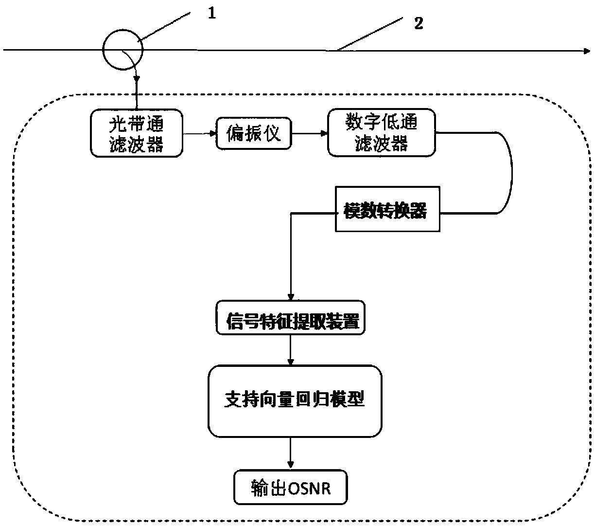
[0027] Such as figure 1 The shown optical signal-to-noise ratio monitoring device includes a signal acquisition device, a signal feature extraction device, and a support vector regression model connected sequentially. The signal feature extraction device is used to extract the signal-to-noise ratio and polarization impairment in the Stokes parameters, and the support vector regression model is a model obtained by training multiple groups of optical signal signal features and corresponding optical signal-to-noise ratio values. The device can be installed at each node in the network. During operation, the signal acquisition device is used to obtain the optical signal transmitted by the optical fiber link 2, that is, the Stokes parameter in the signal to be tested, and the signal feature extraction device extracts the Stokes parameter in the Stokes parameter. Signal-to-noise ratio and polarization-damaged signal features, the above-mentioned extracted signal is input into a suppo...

Embodiment 2

[0029] Based on the principles of the foregoing embodiments, this embodiment refines its implementation manners.

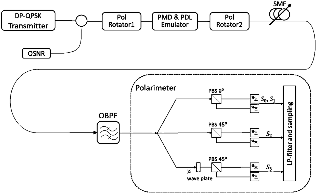
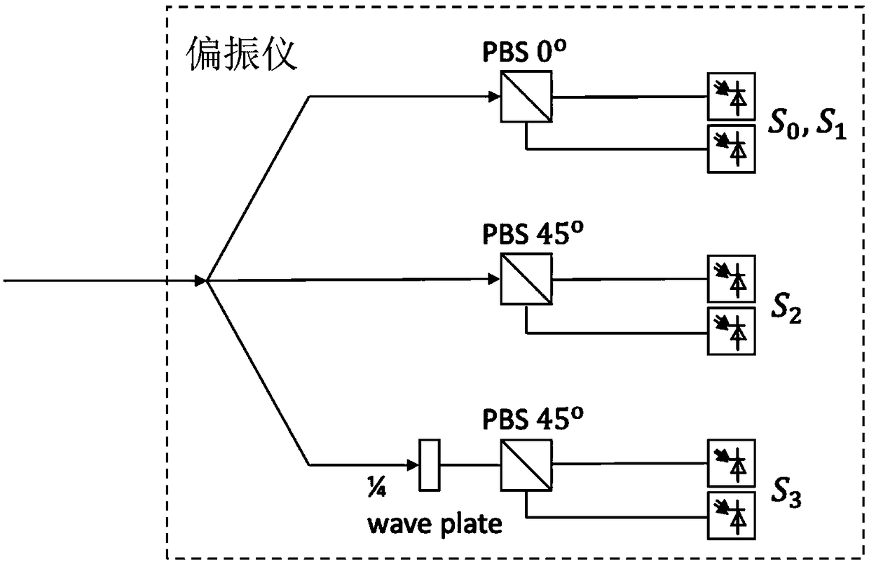
[0030] The signal acquisition device includes a signal separation device, a signal detection device, a low-pass filter, and an analog-to-digital converter connected sequentially. The signal separation device can use a 99:1 directional coupler 1, the polarization multiplexed optical signal containing spontaneous emission ASE noise transmitted in the wavelength division multiplexing WDM optical communication network, after being separated by the directional coupler, through the adjustment of the optical bandpass filter The bandwidth of the filter is to allow only one optical signal channel to pass without affecting its adjacent channels; the signal detection device can be implemented with a polarimeter to obtain continuous Stokes parameters in the polarization multiplexed optical signal; the low-pass filter can be used A digital low-pass filter is used for continuou...


PUM


Abstract

The invention discloses an optical signal-to-noise ratio monitoring device and an optical signal-to-noise ratio monitoring method. The optical signal-to-noise ratio monitoring device comprises a signal acquisition device for acquiring a Stokes parameter of a to-be-monitored signal, a signal feature extraction device for extracting signal-to-noise ratio and polarization damage in the Stokes parameter, and a support vector regression model obtained by training with an optical signal feature parameter and an optical signal-to-noise ratio value corresponding to the optical signal feature parameter. The optical signal-to-noise ratio monitoring device realizes optical signal-to-noise ratio monitoring through acquiring the Stokes parameter and extracting the signal-to-noise ratio and the polarization damage based on a support vector regression machine, is simple in structure and low-cost, can be widely deployed at each node in a network and can provide information basis for resource allocation and dynamic routing in an optical network.

Description

technical field [0001] The invention relates to the field of optical communication devices, in particular to an optical signal-to-noise ratio monitoring device and a monitoring method. Background technique [0002] Since the backbone network needs to achieve large capacity, high bandwidth, high speed and long-distance transmission, this puts forward higher requirements for the transmission capacity and performance maintenance of modern optical communication systems. Practical optical networks often use high-order modulation format signals and technologies such as wavelength division multiplexing, frequency division multiplexing, and polarization multiplexing to achieve large-capacity, high-speed data transmission. During the transmission process, since the power of the signal will continuously decrease, the quality of the signal will also continuously deteriorate. Therefore, in order to achieve low-cost and long-distance transmission in modern optical fiber communication sy...

Claims


Application Information

Patent Timeline
Patent Type & Authority Applications(China)
IPC IPC(8): H04B10/079H04B10/2569G06K9/62
CPCH04B10/07951H04B10/07953H04B10/2569G06F18/2411
Inventor 彭云峰吉同晖
Owner UNIV OF SCI & TECH BEIJING
Learn More